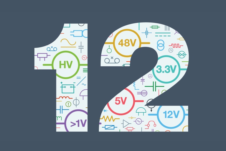
48V 迁移之路上的 12 项技术挑战
为帮助您为迁移到 48V 做好更充分的准备,以下梳理了 12 项需要重点关注的挑战
降压调节是将 DC 电源的电能分配至负载点(PoL)的关键环节,传统上通常采用脉宽调制(PWM)电路来实现,也就是通过改变 PWM 的占空比来满足所需的降压要求。
然而,有若干因素给稳压器设计带来了日益增加的压力。首先,随着更强大的器件不断被集成到电路板上,而电路板的尺寸却并未相应增加,导致功率密度被迫提高。其次,为了降低配电损耗,DC 电源电压趋于升高,而器件电压则在降低以提高内部运行速度和效率。这两种趋势叠加,共同增加了稳压器两端的压降及相关的开关损耗。
例如,一个过程控制系统可能需要将电压从 24V 调节至 3.3V——如此大的压差通常需要两级调节;这会增加电路板空间和成本并带来可靠性问题。此外,稳压器的开关频率也受到限制,因为开关操作增多会带来更多损耗。这反过来又限制了使用更小的无源元件进行滤波,从而降低了整体解决方案的功率密度。
尽管高密度 PWM 稳压器已随着 IC 集成度、MOSFET 和封装技术的优化而不断发展,但其设计已不足以满足所面临的功率需求。这主要是由于稳压器 MOSFET 内的开关损耗。要显著提升稳压器性能,必须克服或避免这些损耗。
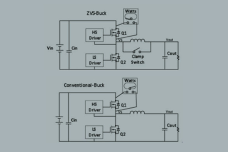
一种更好的解决方案是采用零电压开关(ZVS)拓扑,它能支持以更高频率和更高输入电压运行,而不会牺牲效率。虽然仍基于 PWM,但在 PWM 时序中增加了一个独立阶段以实现 ZVS 操作。图 1 比较了传统的降压稳压器和为 ZVS 操作而改进的版本。利用新增的相位,ZVS 拓扑通过钳位开关和电路谐振,以软开关方式高效地运行高压侧(Q1)和同步(Q2)MOSFET,从而避免其在传统 PWM 操作和时序过程中产生的损耗。
例如,在传统电路中,当 Q1 导通、Q2 关断时,由于 Q2 的体二极管在其反向恢复时间内呈现短路状态,会有非常大的尖峰电流流经这对 MOSFET。其他损耗则源于 Q1 输出电容的放电以及 Q2 的反向恢复。这些损耗会随着开关频率或输入电压的增加而增加。
相比之下,ZVS 设计在高压侧 MOSFET 导通前,消除了由体二极管导通引发的大电流,解决了传统稳压器的高导通损耗问题,将高压侧 MOSFET 的 D-S(漏-源)电压降至零或接近零,从而不会产生大电流尖峰或有害的振铃。施加于 Q1 上的 ZVS 操作消除了其导通时的米勒效应,从而允许使用尺寸更小的驱动器和更低的栅极驱动电平。
Vicor 已在其降压稳压器产品中采用了 ZVS 拓扑。相比传统硬开关高密度稳压器,这些产品能以高达 36VIN 的输入电压、更高的效率以及更小的外形尺寸提供稳压调节。
图 1: ZVS Buck
图 1: ZVS Buck
相关内容
产品概述:降压稳压器
48V 迁移之路上的 12 项技术挑战
为帮助您为迁移到 48V 做好更充分的准备,以下梳理了 12 项需要重点关注的挑战
革新高压移动供电的电气化之路
ReVolt 为电影片场注入活力!了解他们如何使用 Vicor 高密度电源模块取代柴油,实现清洁的移动供能
电源架构为何制约新太空 AI 任务
卫星 AI 的发展速度已经超越了传统电源系统。现代计算需要超低电压、大电流的供电能力,而传统电源架构直到现在都无法满足这一需求
AI 在太空赋能快速通信,开启创新新纪元
Spacechips 携手 Vicor 打造了 AI1 应答器,这是目前在轨运行中功率密度最高的处理器板。分比式电源架构可提供 133 TOPS 算力用于实时卫星自主运行和 130A 处理