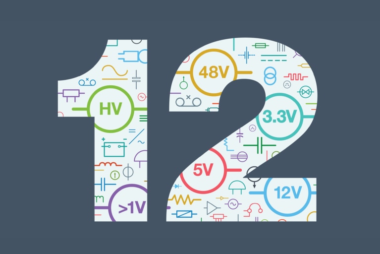
48V 遷移之路上的 12 項技術挑戰
為幫助您為遷移到 48V 做好更充分的準備,以下梳理了 12 項需要重點關注的挑戰
降壓調節是將 DC 電源的電能分配至負載點(PoL)的關鍵環節,傳統上通常採用脈寬調製(PWM)電路來實現,也就是通過改變 PWM 的占空比來滿足所需的降壓要求。
然而,有若干因素給穩壓器設計帶來了日益新增的壓力。 首先,隨著更强大的器件不斷被集成到電路板上,而電路板的尺寸卻並未相應新增,導致功率密度被迫提高。其次,為了降低配電損耗,DC 電源電壓趨於升高,而器件電壓則在降低以提高內部運行速度和效率。 這兩種趨勢疊加,共同新增了穩壓器兩端的壓降及相關的切換損耗。
例如,一個程序控制系統可能需要將電壓從 24V 調節至 3.3V——如此大的壓差通常需要兩級調節; 這會新增電路板空間和成本並帶來可靠性問題。 此外,穩壓器的切換頻率也受到限制,因為切換操作增多會帶來更多損耗。 這反過來又限制了使用更小的無源元件進行濾波,從而降低了整體解決方案的功率密度。
儘管高密度 PWM 穩壓器已隨著 IC 集成度、MOSFET 和封裝技術的優化而不斷發展,但其設計已不足以滿足所面臨的功率需求。 這主要是由於穩壓器 MOSFET 內的切換損耗。 要顯著提升穩壓器效能,必須克服或避免這些損耗。
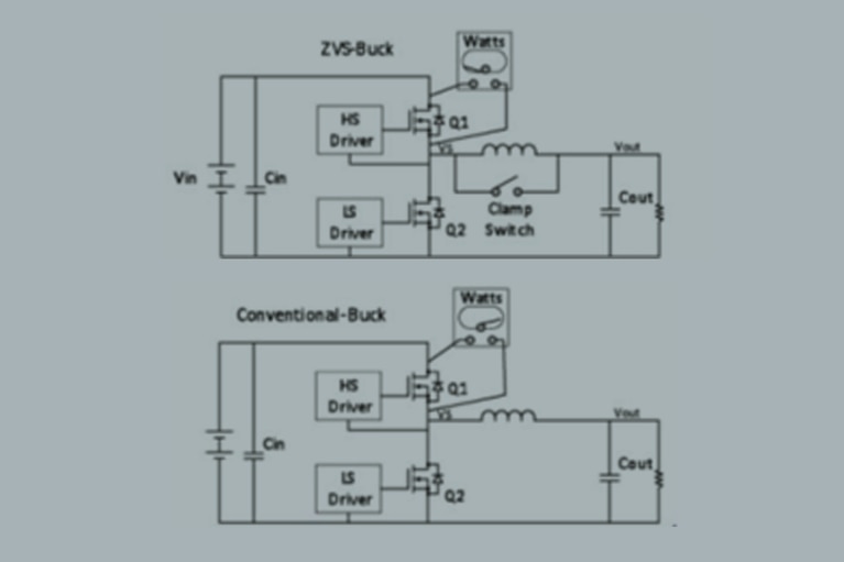
一種更好的解決方案是採用零電壓開關(ZVS)拓撲,它能支持以更高頻率和更高輸入電壓運行,而不會犧牲效率。 雖然仍基於 PWM,但在 PWM 時序中新增了一個獨立階段以實現 ZVS 操作。 圖1比較了傳統的降壓穩壓器和為 ZVS 操作而改進的版本。 利用新增的相位,ZVS 拓撲通過鉗比特開關和電路諧振,以軟切換方式高效地運行高壓側(Q1)和同步(Q2)MOSFET,從而避免其在傳統 PWM 操作和時序過程中產生的損耗。
例如,在傳統電路中,當 Q1 導通、Q2 關斷時,由於 Q2 的體二極體在其反向恢復時間內呈現短路狀態,會有非常大的尖峰電流流經這對 MOSFET。 其他損耗則源於 Q1 輸出電容的放電以及 Q2 的反向恢復。 這些損耗會隨著切換頻率或輸入電壓的新增而新增。
相比之下,ZVS 設計在高壓側 MOSFET 導通前,消除了由體二極體導通引發的大電流,解决了傳統穩壓器的高導通損耗問題,將高壓側 MOSFET 的D-S(漏-源)電壓降至零或接近零,從而不會產生大電流尖峰或有害的振鈴。 施加於 Q1 上的 ZVS 操作消除了其導通時的米勒效應,從而允許使用尺寸更小的驅動器和更低的柵極驅動電平。
Vicor 已在其降壓穩壓器產品中採用了 ZVS 拓撲。 相比傳統硬開關高密度穩壓器,這些產品能以高達 36VIN 的輸入電壓、更高的效率以及更小的外形尺寸提供穩壓調節。
圖 1:ZVS Buck
圖 1:ZVS Buck
相關內容
產品概述:降壓穩壓器
48V 遷移之路上的 12 項技術挑戰
為幫助您為遷移到 48V 做好更充分的準備,以下梳理了 12 項需要重點關注的挑戰
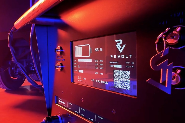
革新高壓移動供電的電氣化之路
ReVolt 為電影片場注入活力!了解他們如何使用 Vicor 高密度電源模組取代柴油,實現清潔的移動供能
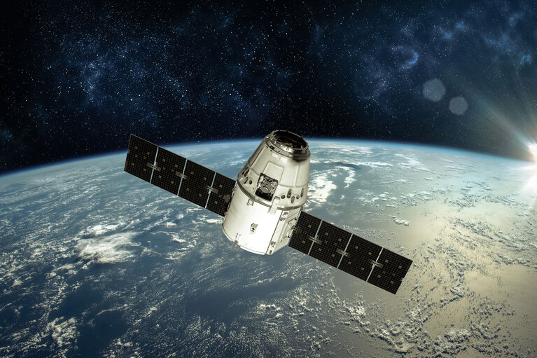
電源架構為何制約新太空 AI 任務
衛星 AI 的發展速度已經超越了傳統電源系統。 現代計算需要超低電壓、大電流的供電能力,而傳統電源架構直到現在都無法滿足這一需求
AI 在太空賦能快速通訊,開啟創新新紀元
Spacechips 攜手 Vicor 打造了 AI1 應答器,這是現時在軌運行中功率密度最高的處理器板。 分比式電源架構可提供 133 TOPS 算力用於實时衛星自主運行和 130A 處理