

2026 年汽車創新日
Vicor 展示了使用緊湊、高功率密度的 DC-DC 轉換的創新優勢
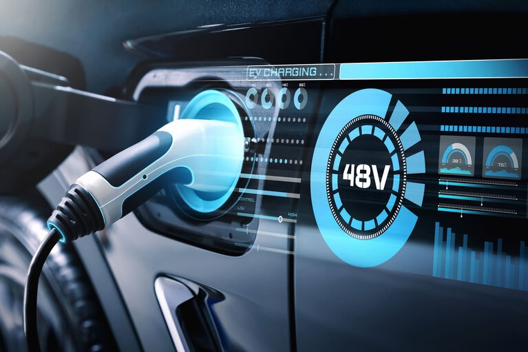
電氣化帶來的經濟效益和生活質量提升推動了高壓(HV)至 48V DC-DC 轉換技術在眾多市場中的應用。隨著電池電壓提升,集成高壓至 48V 轉換的電源模組在電動汽車和其他應用中越來越普遍。瞭解雙向固定比率母線轉換器模組如何優化系統供電。
作者:Maury Wood,Vicor 公司戰略營銷副總裁
在多個行業中機器電氣化所帶來的全新且具有挑戰性的使用場景中,高功率密度的雙向 DC-DC 轉換器是理想的解決方案。本文介紹了高效的固定比率 DC-DC 轉換器模塊如何支持瞬態回收負載,而無需昂貴且複雜的液冷系統。
電氣化,即全社會從化石燃料驅動的機器轉向電力驅動的趨勢,正在席捲所有工業、車輛以及航空航太/國防設備領域。推動這一趨勢的經濟和文化因素廣為人知且是普遍公認的。電氣化既有環保優勢(例如减少相關的碳排放),也帶來了關鍵的性能提升優勢,例如大扭矩電機能够提升電動汽車的加速性能[1][2]。
電氣設備和電動汽車通常使用從 270V 到高達 1000V 的高壓直流電,以减少電源與負載(包括線性/旋轉電機、執行器、感測器、處理器以及負載點低壓穩壓器等)間母線或線纜的功率損耗。高壓系統還能實現高水准的機械力轉換,包括線性位移和旋轉位移。
DC-DC 轉換器在將高壓轉換為低壓方面扮演著關鍵角色,支持隔離或非隔離、穩壓及反向操作,廣泛應用於電動汽車、資料中心、通信系統及各類工業設備中。這些電源轉換器可以通過分立式元件或模組化封裝形式實現。本文重點討論 DC-DC 轉換器電源模組。
以前,占主導地位的直流子系統供電網路(PDN)電壓為 12V。而過去大約 10 年中,隨著負載功率需求的激增及遵從安全特低電壓(SELV)安全標準的必要性,整個行業開始向 48V(資料中心中為 54V)過渡,催生了高壓至 48VDC 轉換器。在這一子系統供電網路(PDN)電壓演變的同時,業界開始採用以 48V 為中心的 DC-DC 轉換器電源模組。這些模組具有諸多優勢,包括易用性、高功率密度、功率可擴充性和輕量化設計,而且支持能量回收(將能量回饋至主電源)。
電解電池採用快速反覆運算的多種化學技術,經常用作高壓與低壓直流電源,顯然是移動(非系留)和手持應用的理想選擇。從鉛酸電池到最新的鈉離子和石墨烯電池,以及現代超級電容器,大多數類型的電池均可充電,因此支持再生能量系統,預計將在全球範圍內實現巨大的節能效益。
目前,電動汽車中常用電池組的標稱電壓為 400VDC 和 800VDC。將來,在能量密度不斷提高的趨勢推動下,800V 電池組或將佔據主導地位。 輕度混合動力汽車通常使用 48VDC 電池,部分廠商則選用 12VDC 多電芯電池組。電動汽車不僅包括乘用車,還涵蓋工業和農用車輛(包括怪手和耕耘機等工程車輛)以及各類休閒載具平臺(如個人水上交通工具、四驅越野車、雪地摩托、機車等)。除了續航里程有限和充電所需時間較長等劣勢外,這些車輛類型的電動版本在最終用戶體驗(如加速性能、扭矩輸出和駕乘品質)方面往往優於內燃機車型。
更高的電壓能够以較低的電流輸出相同的功率。由於配電功率損耗(通常使用銅或鋁母線或電纜)與電流的平方成正比(P = I²R),因此在高功率應用中,可以通過使用更高的配電電壓來减少由母線和電纜電阻引起的大量傳導損耗。 母線和電纜的線規是根據電流承載能力(安培容量)確定的。電壓提高 4 倍,電流减小 4 倍,對尺寸、重量和成本有顯著影響。例如,要傳導 200A 的電流,銅母線的橫截面積需要達到大約 0.0625 平方英寸; 而要傳導 800A 的電流,導線的橫截面積需要達到大約 0.3125 平方英寸,相差五倍[3]。48VDC 供電網路中使用的母線和電纜比 12VDC 供電網路中所用的線纜更細、更輕,因此成本更低。
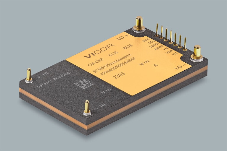
先進的 48V 電源模組憑藉其技術能力,正在解鎖新的效率和性能水准。例如,Vicor BCM6135 是一個固定比率隔離式(4242V)母線轉換器電源模組系列,集成了磁性元件,設計本身具有雙向轉換功能,支持再生電池應用。
該系列包含一種額定穩態功率為 2.5 kW 的模組,其比率轉換“K 因數”(相當於變壓器的匝數比)為 1/16,用於將將標稱 800V 的電壓轉換為 50V。
該模組採用先進的電路拓撲和零電壓開關(ZVS)及零電流開關(VCS)技術,其峰值效率高達 97.3%,意味著輸入功率中只有 2.7% 轉化為熱損耗(約 2.7% x 2.5 kW 的熱功率)。在峰值功率為 3.1kW 且設備外殼溫度(TCASE)保持在 70°C 時,這些熱量需要通過適當的熱管理進行散熱。它的體積功率密度高達 159kW/L(模組尺寸為 61.3mm x 35.4mm x 7.3mm); 模組重量為 58g,連續質量功率密度為 43.1W/g。
圖 1:BCM6135 母線轉換器模組。
BCM6135(如圖 1 所示)支持暫態雙向啟動和穩態運行。此外,它可用作電容倍增器,將高壓(HI)母線上的大容量電容按 K 因數的平方(16²= 256)縮放到低壓(LO)母線。該特性節省了低壓母線上原本所需的旁路電容或大容量電容的成本、重量和空間
此外,該 BCM® 的高開關頻率使其具備極快的負載階躍瞬態效能(di/dt),達到 8 MA/s,因此可以替代輔助電池和超級電容器,可在高性能計算和電動汽車等苛刻應用中支持瞬態負載階躍。
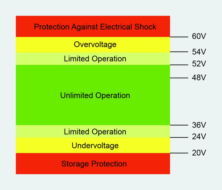
該 BCM 具有很寬的輸入電壓範圍(520V 至 920V),可以支持廣泛的直流電壓配電標準。寬輸入電壓範圍是 BCM 中採用的專有正弦振幅轉換器™(SAC™) 拓撲的特性之一。寬輸入電壓範圍的意義重大; 這在德國汽車工業協會(VDA)的推薦中得到了很好的闡釋。VDA 320《機動車電氣和電子元件 -48V 車載電源 - 要求與測試》(2025 年 1 月 20 日版),也稱為 LV 148,由奧迪、寶馬、戴姆勒、保時捷和福斯等汽車 OEM 共同製定,作為 48VDC 電壓範圍元件的通用 OEM 標準[4]。該指南建議,電池在 36V 至 52V 之間應支持無限的工作電壓範圍,在 24V 至 54V 之間應支持有限的工作模式(如圖 2 所示)。
圖 2:VDA 320 48VDC 電壓範圍推薦(圖片來源:VDA)
薄型(7.3mm)BCM6135 模組系列採用覆模和電鍍工藝以提升熱敏捷性,並通過表面貼裝端子或通孔引脚進行遮罩和互連,其三維互連(3DI)ChiP™ 封裝具有低熱阻和高熱適應性,包括連接散熱器和冷板的共面熱介面[5]。
在 70°C 的高溫環境中,輸出電流為 50A、輸出電壓為 48V 的情况下,BCM6135 的轉換效率通常為 97.3%。這種高壓至 48V 電源轉換模組常用於持續負載應用,但也非常適合瞬態脈衝負載應用,而且根據負載的脈衝占空比,有可能使用被動冷卻(無需強制風冷或液冷)。再生電動汽車主動懸掛(可與主動防側傾控制結合)是一個具有瞬態特性的典型雙向使用場景。驅動主動懸掛的線性電機僅在遇到顛簸和坑窪時才被啟動。這種系統應用最好使用峰值功率轉換名額來建模和描述。
過去的事實證明,由於尺寸、重量和成本限制,12VDC 不足以驅動主動懸掛電機。 需要注意的是,電動汽車的 800VDC 主電池可用於為主動懸掛子系統供電,但將 800VDC 電源連接到車輛週邊會降低安全性,對參加事故救援的急救人員而言尤其如此。
這款 BCM6135 型號的保證峰值額定功率為 3.1kW,持續時間為 20ms,占空比 25%,適用於其工作電壓範圍的低端(即低線運行;完整持續工作範圍為 17V 至 57.5V)。和預期的一樣,峰值功率輸出在瞬態需求持續較長時間內會降低。為主動懸掛開發應用級峰值功率規格是一項非常複雜的工作,因為最壞情况下的路况、冷卻方法、尺寸、重量和成本限制目標的變化可能非常大。然而,為了盡可能减小尺寸、減輕重量和降低成本,汽車廠商通常傾向於使用被動散熱方法(即傳導/對流散熱器,但無風扇強制風冷或循環液冷板)來為主動懸掛 DC-DC 轉換器子系統散熱。
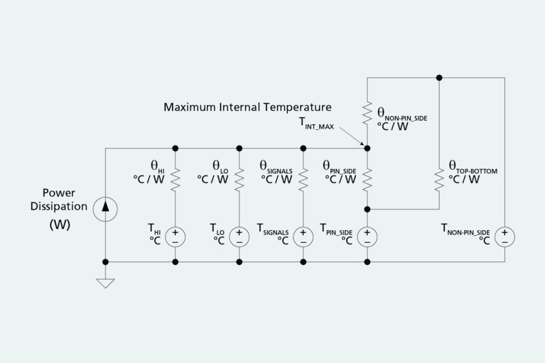
要使設計滿足這些約束條件,挑戰在於驗證電源轉換器模組能够滿足峰值瞬態負載需求,而不會因過熱而導致模組關閉。BCM6135 的兩面均經過電鍍處理,理想情况下散熱器應同時接觸封裝的兩面。該模組的封裝熱容為 44.5 J/K,配備有一個內部溫度感測器,結合雙面熱模型[6],可估算內部 MOSFET 的最高“結”溫,如圖 3 和圖 4 所示。
圖 3:基於電路元件等效法的 BCM6135 雙面冷卻熱阻模型。
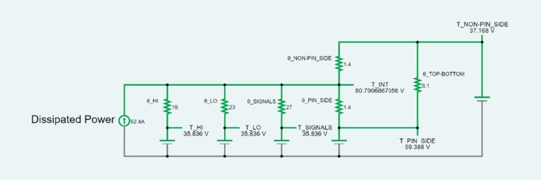
圖 4:BCM6135 雙面注釋熱阻模型及其元件值注釋。
熱容用於計算模組在瞬態熱事件期間的熱時間常數。該時間常數是熱容與熱阻的乘積。產品資料手册中給出的熱容值是一個計算值,假設產品在瞬態熱事件期間內部(整個模組)始終保持均勻的溫度。這是一種線性化的簡化,但它使產品設計師能够在產品設計週期的早期快速估算產品溫度隨時間變化的行為。內部溫度均勻的簡化處理還意味著,當使用散熱器對 48V 電源模組進行雙面冷卻時,熱時間常數能更好地反映實際產品性能。
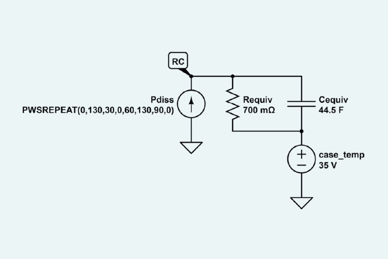
例如,圖 5 顯示了類比 BCM6135 熱阻的等效電路[7]。電阻器類似於熱阻,組織為攝氏度每瓦[°C/W]。電流源類似於熱源,組織為瓦[W]。電壓源在此電路模型中類似於溫度源,組織為攝氏度[°C]。
圖 5:BCM6135 熱模型等效電路假設封裝頂部和底部均進行冷卻,等效熱阻為 0.7°C/W,外殼溫度為35°C。
該等效電路假設封裝頂部和底部均進行冷卻,等效熱阻為 0.7°C/W,外殼溫度為 35°C,模組的熱容為 44.5J/K,並且模組在 30 秒開、30 秒關的持續重複脈衝期間耗散 130W 的功率。
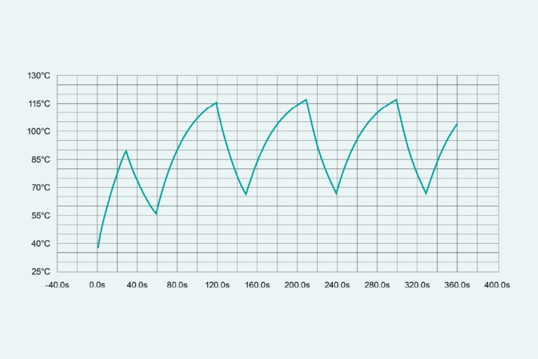
該電路的類比結果如圖 6 所示; 運行條件如下:VHI 為 520,VLO 為 32.5,低側峰值輸出電流為 80A(峰值輸出功率為 2.6kW)。在第一個功率脈衝期間,最大內部溫度升高至約 90°C。下一個脈衝顯示最高內部溫度升高至約 115°C。重複脈衝顯示最高內部溫度保持在約 115°C 左右。
圖 6:在以下運行條件下類比的 BCM 脈衝功率熱力學:VHI 為 520,VLO 為 32.5,低側峰值輸出電流為 80A。第一個功率脈衝顯示最高內部溫度升高至約 90°C,隨後升高至約 115°C。重複脈衝顯示最高內部溫度限制在約 115°C。
應始終對模組進行應用測試,以驗證初始建模估算的瞬態效能,並正確設計被動對流散熱器。
BCM6135 本身具有雙向轉換功能,可暫態切換工作方向。無論電流流向如何,模組的轉換效率保持一致。
在再生主動懸掛應用中,當車輛在平坦的路面上行駛時,800V 電池作為電流來源,懸掛驅動電機為 48V 負載。當車輛經過坑窪路段時,懸掛系統中的電機暫時變為發電機(壓縮),BCM 低側的電壓升高到 800V 電池電壓除以轉換 K 因數(此應用中 K = 1/16)以上。這種電位差促使母線轉換器切換電流流動方向,而無需內部回路控制器干預。 隨後,800V 電池暫時成為負載(回彈),通過其電池管理系統電路充電來恢復電能。
坑窪路段引起的位移消退後,母線轉換器將再次將 800V 電池降壓,並為懸掛系統的線性電機供電。所有這些操作均無需車輛的車載處理器進行干預。這些懸掛驅動器的頻率範圍約為 1Hz 至 10Hz。有趣的是,道路表面的起伏本質上類似於母線轉換器負載階躍響應的動態性。
母線轉換器高側與低側之間的電位差决定電流幅度和方向。
想像一下,低側的負載是無源負載(如電阻器),而高側有一個電勢為 800V 的電池。BCM 相當於一個 K = 1/16 的變壓器,在低側生成 50V 的電勢。 電流將流經該電阻器,其大小由施加在電阻器上的電壓决定。
如果在低側添加一個電勢為 51V 的電源並替換電阻器,則 BCM 輸出(50V)與該電源(51V)之間的電位差將變為負值(-1V),電流將開始反向流動。該電流的大小將由 BCM 內部和電池的總路徑電阻决定。
這可以被直觀地理解為將 BCM 的高側連接到 800V 電源,將低側連接到一個雙向電源。 通過使雙向電源的電壓變化 ±100mV,電流將在兩個方向上交替流動,峰值電流的大小為 100mV 除以 BCM 輸出電阻。在這些假設條件下,如果母線轉換器的輸出阻抗為 25mΩ,將產生約 4A 的雙向峰值電流(如圖 7 所示)。
圖 7:母線轉換器雙向電流流動示波器螢幕截圖:通過使雙向電源的電壓變化 ±100mV,母線轉換器電流將在兩個方向上交替流動,峰值電流將為 100mV 除以 BCM 的輸出阻抗。母線轉換器的輸出阻抗典型值為 25mΩ,因此在這些假設條件下,可獲得約 4A 的雙向峰值電流。。
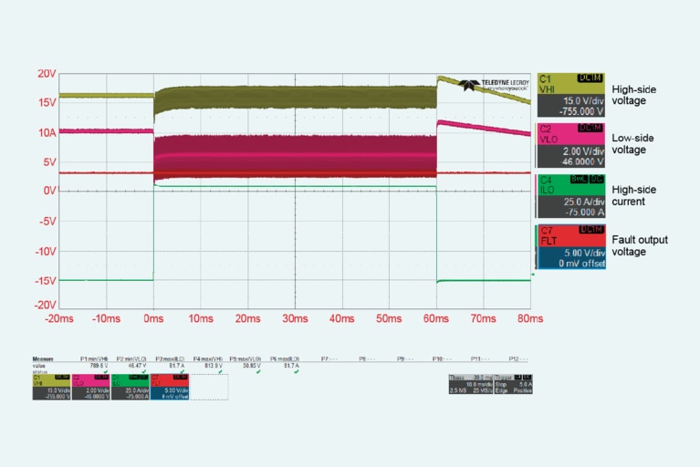
在實驗室測試中(如圖 8 所示),BCM6135 的峰值功率為 4kW(50V 時 80A),持續 60ms,表明該模組設計在動態負載下具有極佳的熱穩定性。
圖 8:示波器螢幕截圖:4kW 持續 60ms。實驗室測試中 BCM6135 展示的峰值功率為 4kW(50V 時 80A),持續時間為 60ms,表明該模組設計在動態負載下具有極佳的熱穩定性。
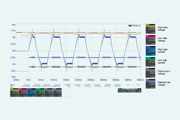
在第二次實驗室測試中(如圖 9 所示),負載以脈衝形式從 16A 切換至 80A,占空比為 10%(900ms 為 16A,100ms 為 80A)。運行條件為 520VHI 和 32.5VLO,這是 BCM6135 支持的電壓範圍的低端。平均功率為 720W(32.5V 時 22A)。在 30 分鐘(1800 秒)的測試過程中,內部感測器的“讀取溫度”(結溫的替代名額)顯示穩態溫度約為 100°C,遠低於允許的最高結溫 125°C。測試設定採用單面散熱器被動冷卻管道。 這進一步證明了目標被動冷卻應用的可行性。
圖 9:10% 的占空比,16A 至 80A 負載階躍,1800 秒後穩態溫度讀數為 100°C(使用單面散熱片)。
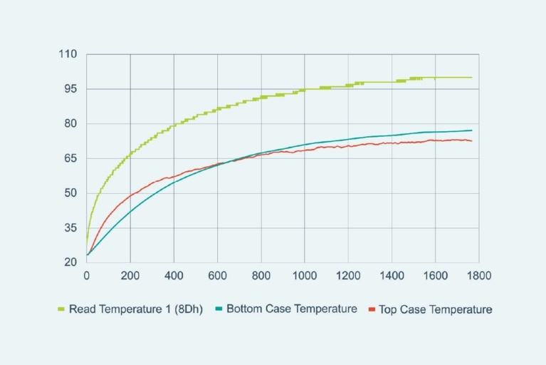
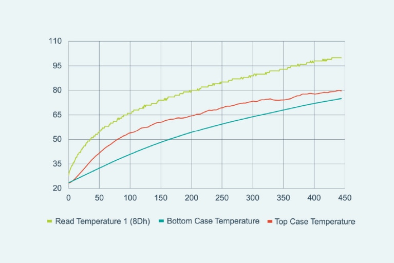
圖 10:平均輸出功率為 1.1 kW,450 秒後讀取的非穩態溫度為 100°C(使用單面散熱器)。
另一方面,在第三次實驗室測試中(如圖 10 所示),使用相同的熱管理設定,平均功率新增至 1.1kW(50V 時 22A)。此測試的運行條件為 800VHI 和 50VLO; 這是 BCM6135 支持的電壓範圍的高端。負載從 17.5A 切換至 70A,占空比為 10%(900ms 為 17.5A,100ms 為 70A)。在 7.5 分鐘的測試時間內,感測器測得的內部溫度為 100°C,且仍在上升(未達到穩態)。但 7.5分鐘(450 秒)的持續時間遠超 20 秒,因此這是一個積極的訊號,表明 BCM6135 可能滿足某些主動懸掛的設計要求。
最終,實驗結果表明,在密封外殼的工作溫度範圍內,使用被動冷卻散熱器時,BCM6135 可支持 1.3kW 的平均功率,持續 30 秒。
主動懸掛的設計目標包括對路面狀況的假設(可緩解的顛簸和坑窪的幅度及持續時間)。 這些假設會直接影響 DC-DC 轉換器所需的峰值功率能力。線性電機的電磁特性也會影響 DC-DC 轉換器的要求。儘管如此,BCM6135 仍是當今主動懸掛、主動防側傾控制 DC-DC 轉換器子系統中不可或缺的母線轉換器模組。
電氣化具有明顯的經濟性和提升生活質量的優勢,正推動著全球各類設備日益採用高壓至 48V DC-DC 轉換。隨著電池電壓的新增和 48V 低壓母線的普及,集成式高壓至 48V 電源模組在電動汽車(EV)和混合動力汽車(HEV)中的應用日益廣泛。
新一代雙向固定比率母線轉換器模組具有出色的電力和散熱效能,能够滿足瞬態再生應用(如電動汽車主動懸掛系統)的苛刻要求。在行業正加速採用更昂貴的液冷供電系統的趨勢下,本文提出的被動冷卻研究結果具有重要意義。
作者衷心感謝 Vicor 的同事在本文撰寫過程中提供的幫助,特別是 Haris Muhedinovic、Lap Nguyen 和 Alexander Parady。
[1] The Slow Road to Electrification of Everything 訪問於 2025 年 2 月 4 日[線上]可查閱: https://www.forbes.com/sites/hessiejones/2023/09/26/the-slow-road-tothe- electrification-of-everything
[2] With Greater Voltage Comes Responsibility 訪問於 2025 年 2月 5 日[線上]可查閱:https://www.fleetowner.com/equipment/media-gallery/ 21134251/with-greater-voltage-comes-greater-responsibility
[3] Ampacities and Mechanical Properties of Rectangular Copper Busbars: Table 1. No. 110 訪問於 2025 年 2 月 4 日[線上]可查閱:https://copper. org/applications/electrical/busbar/bus_table1.php
[4] VDA 320 (01/2015) 訪問於 2025 年 2 月 6 日[線上]可查閱:https:// webshop.vda.de/VDA/en/vda-320-012015
[5] Automotive Power Modules 訪問於 2025 年 2 月 6 日[線上]可查閱: https://www.vicorpower.com/all-products/automotive
[6] Thermal Models of Vicor Power Components 訪問於 2025 年 2 月 10 日[線上]可查閱: https://www.vicorpower.com/documents/whitepapers/ wp-Thermal-Models-Vicor-Power-Components.pdf
[7] Thermal Management for VIA™ and ChiP™ Modules 訪問於 2025 年 2 月 10 日[線上]可查閱:https://www.vicorpower.com/documents/application_ notes/an_Thermal_Management_VIA_ChiP_Modules.pdf.
本文最初由 IEEE Power Electronics Magazine 發佈。
Maury Wood 是 Vicor 公司的戰略營銷副總裁。加入 Vicor 之前,Maury 曾在 EXFO、AFL、Broadcom、NXP、Analog Devices 和 Cypress 等光纖測試和電晶體公司擔任高級職務。他擁有密歇根大學電子工程學士學位,並在東北大學、巴布森學院和麻省理工學院攻讀研究生課程。他喜歡登山、越野滑雪、騎山地自行車和爵士貝司。
作者:Maury Wood,戰略營銷副總裁