Digitimes 无人载具技术关键路径研讨会
了解更多关于无人机高密度电源转换的详情
传统的太空电源拓扑假设电流密度适中、负载阶跃缓慢且运行模式静态。而 AI 工作负载全面打破了这三重假设。结果显而易见:在传统“母线+负载点”(POL)方案下,对于面向 AI 级处理的新太空任务,决定其成败的往往已不是计算能力,而是供电能力。
作者:Ken Coffman,高级现场应用工程师
卫星设计人员已经跨过了一道门槛。我们不再仅仅是将“多一点 DSP”送入轨道,而是部署与地面边缘服务器比肩的星载计算平台,能以数百 TOPS 的算力运行 AI 推理、自适应波束成形、动态频谱管理,以及实时分析。到了这个级别,任务能力的硬性天花板已不是处理器数据手册上的参数,而是电源架构能否在一个狭小、散热困难且暴露于辐射环境中的外壳里,以微秒级瞬态响应性能,输出数百安培的 sub-volt 电源轨。
传统的太空电源拓扑并非为这种运行模式而设计。它们假设电流密度适中、负载阶跃缓慢且运行模式静态,而 AI 工作负载会同时打破这三项假设。结果显而易见:在传统的“母线+ POL”方案下,对于面向 AI 级处理的新太空任务,决定其成败的往往已不是计算能力,而是供电能力。
现代低轨(LEO)有效载荷,被要求在轨完成推理、压缩、路由和自主控制等任务——这些功能在过去严格属于地面站范畴。要高效实现这些,设计人员不得不选用超深亚微米 FPGA、自适应计算加速平台和定制 ASIC,而这类器件的核心电压持续走低,电流需求却不断攀升。
Spacechips AI1 处理器(AI1 Transponder)为任何电源架构都提供了一个切实的压力测试样本。它是一款耐辐射、支持 AI 的处理器卡,在轨 AI 吞吐量高达 133 TOPS,信号处理和机器学习任务直接在轨完成,无需依赖地面站。其主 AI 电源轨工作电压约为 0.8V,时域电流在 130A 到 150A 之间,恰好落在传统“母线+ POL”方案效率低且散热难的区间。
这类负载并非“温和”类型。AI 加速器在空闲、推理和突发模式之间频繁切换,产生快速且不连续的电流阶跃。在这种环境下,电压下降、振铃或噪声会直接导致时钟速率降低、裕度缩减和算力浪费。由于局部去耦受限于体积、质量和 MLCC 可靠性等因素,上游供电网络必须承担瞬态响应的主要重任。
在新太空领域,常规的设计参数环环相扣、彼此掣肘。为了控制发射成本,平台不断缩小;卫星尺寸减小意味着可收集的电力变少,而工作负载却在上升。供电链路中每浪费一瓦,有效载荷便少一瓦可用——运营商越来越不愿意让出这份裕量。
热限制对供电网络(PDN)提出了高电流密度的要求。平面走线、过孔和线束中的 I²R 损耗随电流平方增长:在几十安培下尚且可行的铜导体,到了数百安培就会变成显著的发热源。太空中没有强制风冷可言,所有废热只能通过结构传导并辐射出去。因此,PDN 的损耗最终体现为机械和质量方面的代价,即需要更大的散热面板、更重的导热路径,以及更复杂的封装。
辐射进一步收紧了限制条件。总电离剂量(TID)引起参数偏移,侵蚀着本就紧张的 sub-volt 电压裕量;单粒子效应(SEE)则可能在系统压力最大的时刻,与负载瞬态相互叠加,引发最恶劣的工况。电源组件必须能够耐受低轨(LEO)和中轨(MEO)任务中典型的辐射暴露,同时又不能引入全耐辐射加固定制方案所带来的成本、质量和进度负担。
大多数传统设计遵循一种经典模式:隔离式 DC-DC 转换器先将航天器母线电压降低,再用低压配电平面向外扇出,最后由本地 PWM 负载点(POL)稳压器在负载附近生成最终的核心电源轨。在中等电流和电压条件下,这套方案可行。但到了 0.8V、100A 以上,就会自缚手脚。
到了某个节点,试图修补这套架构已无法奏效。其结构本身就不适配当前的负载压力。
Spacechips 决定彻底替换旧拓扑,而非尝试对其进行优化。他们与 Vicor 合作,采用 Vicor 分比式电源架构(FPA™)及专为低轨(LEO)和中轨(MEO)任务设计的耐辐射模块,实现了电流倍增方案,如图 1 所示。

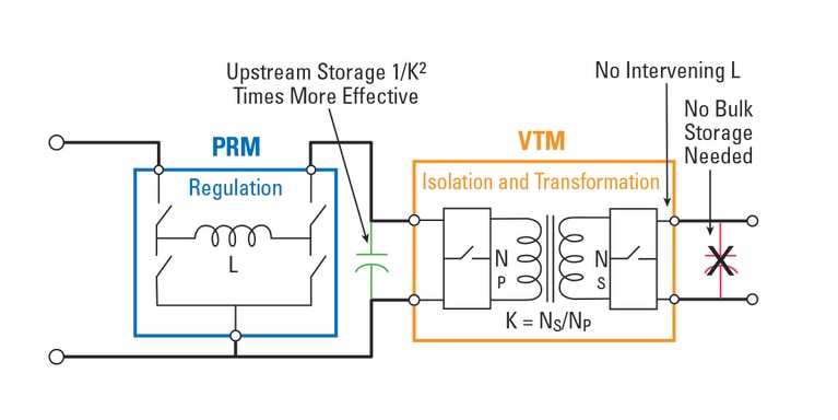
图 1:Vicor 分比式电源架构(FPA)。
电流倍增技术将 DC-DC 转换功能拆分为独立电源模块。Vicor 耐辐射拓扑将电源转换任务划分为三个环节:电压变换与隔离(BCM)、负载电压调节(PRM)和供电(VTM)。该配置有效降低了“最后一厘米”的铜损,同时赋予布局工程师更大的灵活性,可将模块安置于空间允许的位置。
Vicor FPA 将电源转换任务特意拆分为两个截然不同的功能:
在给定功率水平下,提高配电电压可降低电流,进而将 I²R 损耗降至电压比率的平方分之一。举个简单例子,在相同导体电阻条件下,采用 100V 母线替代 12V 母线传输同等功率,电流可降至原来的约 8.3 分之一,理想铜损可降至原来的约 69 分之一。
在实际工程中,航天器电源系统普遍采用 28V 母线;而高功率的新太空设计正越来越多地转向 100V 等更高的母线电压,以进一步降低配电损耗。即便仅从 12V 提升至 28V,配电电流亦可降至原来的二分之一以下,I²R 损耗降至原来的约四分之一至五分之一;而从 28V 提升至 100V,在相同功率下,电流进一步降至原来的约 3.6 分之一,阻性损耗降至原来的约 13 分之一。这,就是“发热濒临极限的背板”与“热设计游刃有余的方案”之间的区别。
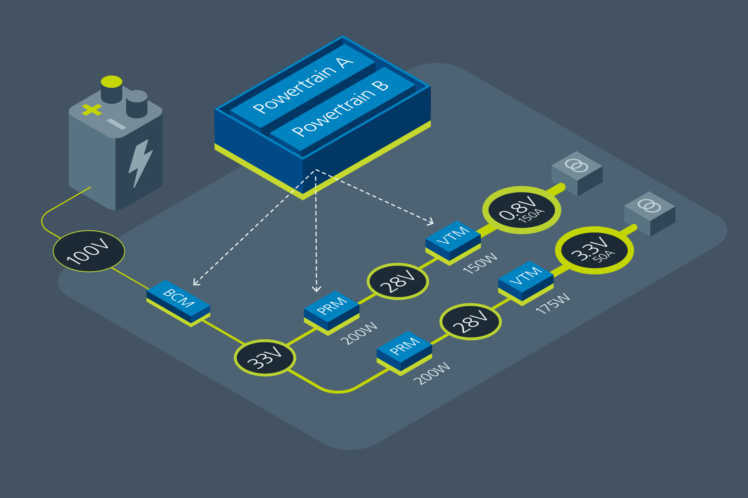
为使上述架构优势更具实感,不妨以与 AI1 电源路径一致的代表性案例加以说明:一条航天器 100V 母线为两路 AI 电源轨供电,一路 0.8V,另一路 3.3V,每路由一个 150W 的 VTM 供电,总计提供 300W 在轨 AI 算力(见图 2)。由于电压变换采用极为紧凑的尺寸实现,并紧邻负载放置,设计人员在组件布局和参数选择方面获得了更大的灵活性。
图 2:分比式电源架构中的储能。
0.8V 下 150W VTM 可提供约 187A 电流;两路此类电源轨即代表在裸片附近提供 300W 的 AI 级功率——此数值尚未计入裕量和转换损耗。如此量级的电流无法经由背板长距离传输;该架构的核心要义,是将数百安培的电流限定在处理器附近一个经过精心设计的极短区域内。
在传统的“母线+ POL”方案中,以采用 12V 中间电源轨驱动两路本地多相稳压器为例,同等 300W 的 AI 算力意味着 12V 平面上约有 25A 电流。在密集的射频与数字混合板卡上,考虑到实际的铜线和过孔电阻,有效配电电阻达到 10mΩ 并非乐观估计。在 25A 电流下,该路径上的 I²R 损耗约为 6.25W,压降 0.25V,占比超过 12V 电源轨的 2%——而此时电流尚未抵达 POL。若未来扩展至 400W 甚至更高,损耗与压降将呈平方级攀升。
AI1 的架构则呈现出截然不同的图景。耐辐射 BCM 从 100V 母线取电,以 3:1 的变比生成 33V 中间电压,可提供高达 400W 的功率,裕量充足,足以驱动两路各 150W 的 PRM:VTM 电源轨。每个 PRM 独立稳压各自的 33V 级中间节点;每个 VTM 再将电压转换为相应的负载点电压。当总功率为 300W 时,33V 配电母线仅承载约 9A 电流,而非 25A。在相同的 10mΩ 有效路径电阻下,I²R 损耗降至约 0.8W,DC 压降约为 0.09V——不足中间电压的 0.3%。配电损耗降至原来的约五分之一至八分之一,电压裕量亦获得了切实可观的恢复——而这一切,仅仅是将繁重的功率传输任务转移至更高电压、更低电流的域,便已实现。
在下游,每个 VTM 将 33V 降压至 0.8V,同时分别实现 32 倍或 8 倍的电流倍增,因此大电流回路(32 倍电源轨中约为 187A)被缩小为仅数厘米长的铜线、过孔区域和专为此密度设计的去耦结构。
最终结果表明:同样的 300W AI 工作负载,在传统架构中使发热严重且稳压不佳的 12V 平面不堪重负;而在 FPA 实现方案中,则由一条相对“凉爽”的 33V 中间母线承载,并为两路本地化电流倍增级供电。AI1 处理器选择了后者,并由此同时恢复了热裕量和电压裕量——而这些裕量在传统方案下,原本会成为制约在轨算力的瓶颈。
将电流倍增级放置在距 FPGA 或 ACAP 仅数厘米处,大电流路径即被大幅收短。中间的铜线短而宽,裸片端的有效输出阻抗较任何等效的 12V 配电 + POL 方案均显著降低。内部冗余的动力系统用于抑制单粒子效应。为抑制单粒子效应,内部动力系统采用冗余设计,集成并自动完成电源轨的监测与控制,设计工程师无需在外部电路中实现该逻辑,如图 3 所示。
图 3:内部冗余动力系统集成并自动完成电源轨的监测与控制。
FPA 模块采用谐振软开关转换技术,与硬开关方案相比,进一步降低了传导与辐射 EMI。谐波含量更低,意味着滤波器件更轻、环路更短,且在适用于新太空平台时,对 DO-160 类传导发射限制可获得更优的设计裕量。
关键在于,该变换级并不依赖缓慢的全局反馈环路来管理瞬态行为。其固定比率工作机制与极低的内阻抗,使其能够在微秒级而非数十或数百微秒内响应突变的电流阶跃,即便在最为严苛的 AI 突发负载条件下,也能将 0.8V 电源轨维持在狭窄的容差范围内。
此外,还具备一项次级优势:电容倍增。电流倍增变压器可将源端观测到的负载侧电容近似按匝数比的平方倍进行放大。在实践中,这意味着在 AI 电源轨处精心布置一组规模适中的 MLCC,其在上游PRM 看来,相当于一个容量大得多的储能池,从而使设计人员能够在满足瞬态响应要求的同时,无需在板卡上布满易碎且存在机械风险的大尺寸陶瓷元件。
电流倍增技术也改变了设计人员在供电网络中应对辐射问题的方式。面向新太空应用的耐辐射 Vicor FPA 模块,已通过低轨(LEO)和中轨(MEO)任务典型辐射水平(数十 krad 总电离剂量)的认证,并采用冗余动力系统和抗单粒子效应控制机制,以确保在单粒子应力下维持正常运行。然而,但更值得关注的是架构层面。
通过将严格稳压功能保持在较高且容差更大的中间电压,并借助负载附近的固定比率变压器处理大电流,该设计有效减少了因辐射引起参数偏移而直接危及 0.8V 裕量的节点数量。稳压级工作在数十伏的电压范围内,具备充足的余量;其漂移和单粒子效应行为可通过常规降额设计与系统级缓解措施加以管控。变换级因不包含复杂的快速反馈环路,本身对控制环路扰动的灵敏度较低。
AI1 实现方案在此基础上增设了一层保障:耐辐射模块集成了双动力系统,允许从任意一侧以全功率驱动负载,并具备自主故障检测与切换功能。面对一个庞大而分散的供电网络,Spacechips 无需对每个分立组件逐一进行加固,而是能够将辐射视为一个系统级问题,借助特征明确的模块化构建模块加以应对。
对于许多低轨(LEO)和中轨(MEO)任务而言,这种耐辐射模块化方案既规避了全耐辐射部件所带来的成本、质量和采购复杂性,同时仍能满足任务可靠性目标。它是一条介于消费级COTS与定制化耐辐射 ASIC 之间的务实折中路径。
随着卫星在轨自主能力不断提升,AI 效用的实际上限越来越取决于电源架构能否在辐射环境中、在严苛的尺寸、重量和功耗预算内,在最恶劣瞬态条件下,提供清洁、严格稳压且大电流的电源轨。Spacechips 与 Vicor 通过摒弃传统低压配电架构,转而采用基于分比式电源架构的电流倍增方案,有效地提升了这一上限。AI1 处理器不只是一块普通的射频板,它表明,在新太空领域,瓶颈已从计算能力转向经过优化的供电能力。
如果在设计供电网络时将处理器视为稀缺资源,则势必会浪费部分计算能力。反之,如果在设计处理器板时,将功率密度、电流分布和辐射行为视为稀缺资源,则可在小型低轨(LEO)卫星上实现服务器级 AI 算力,同时仍能满足热管理与可靠性预算的限制。这便是这一代任务正在倒逼的架构变革,而电流倍增技术正是实现该目标的一种方式。
本文最初由 Signal Integrity Journal 发布。
Ken Coffman,高级现场应用工程师,负责 Vicor 的 New Space 项目。他目前居住在亚利桑那州凤凰城。如您想联络 Ken 可发送邮件至 kcoffman@vicr.com。
Ken Coffman,高级现场应用工程师