


電流倍增器:為 AI 處理器及其他嚴苛應用供電的明智之選
AI 處理器需要解决低電壓、高電流的嚴苛挑戰,這將會導致電源系統設計產生瓶頸。瞭解 Vicor 的電流倍增技術如何改變這一現狀
可靠電源是網路設備提供高可靠性和可用性的關鍵因素。
作者:Yutaka Mitzutani,Vicor 公司現場應用工程師
云計算服務的快速普及推動了數據流量的急劇增長。這一趨勢預計將持續下去,2024 年至 2033 年期間的複合年增長率(CAGR)將達到約 20%。 網路設備,包括路由器和網路交換機,是適應這一快速增長的關鍵,在促進物聯網數據流動方面發揮著重要作用。
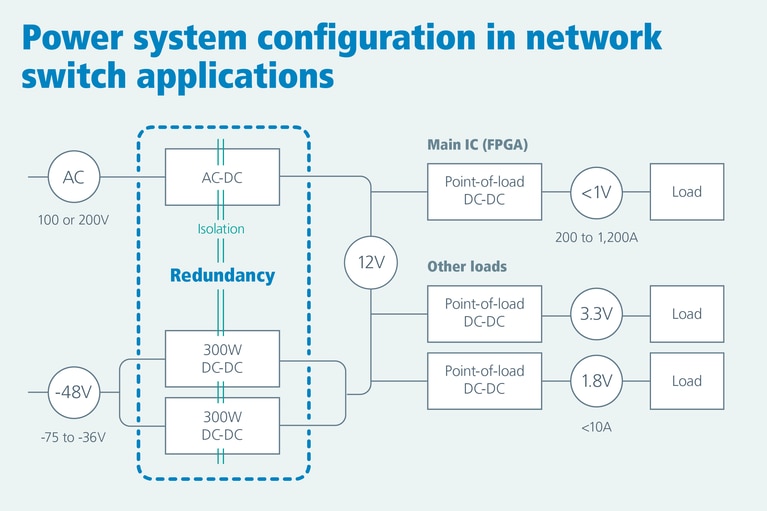
為了保證大量數據的不間斷傳輸和低延遲,網路設備需要具備高可靠性和可用性,而電源系統是實現這一目標的基石。雖然 -48VDC 是網路基礎設施的傳統標準輸入電壓,但網路設備通常以正電壓運行。因此,業內使用隔離式 DC-DC 轉換器來將負電壓輸入轉換為正電壓輸出。在發生故障時,這些轉換器的備援設計對於保持系統正常運行至關重要。 (如圖 1 所示)
圖 1:在對電壓和電流有一定要求的典型網路交換機電源軌配寘中,備援是保證可靠性的重要措施。
網路交換機通常由外部 -48V 直流電源供電。然而,這一輸入電壓可能會出現顯著波動,範圍在 -36V 至 -75V 之間。DC-DC 轉換器必須在此寬泛的輸入電壓變化範圍內保持穩定的 12V 輸出電壓。
某些電源模組可能難以在整個輸入電壓範圍內保持穩定的輸出,儘管它們標示的輸入電壓範圍為 -36V 至 -75V。當輸入電壓達到下限時,這些模組可能無法提供持續的 12V 輸出電壓。
相比之下, Vicor DCM™ 模組能够在 -36V 至 -75V 的整個輸入電壓範圍內保持穩定的 12V 輸出電壓。Vicor DCM3623 通過初級側的專有 Vicor 控制器 IC 主動調節輸出電壓,從而實現這一目標。DCM3623 的輸入電壓與輸出電壓之間的關係可以通過 Vicorpower.com 上提供的產品仿真工具(Product Simulators)查看。
Vicor DCM3623E75H13C2T00 是一款高性能 DC-DC 轉換器,非常適合滿足這些苛刻的要求。它具有高功率密度和並聯運行能力,因此是高密度網路交換機電源系統的理想選擇,尤其是在大規模資料中心內。本文將深入探討該產品的具體特性。
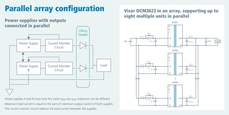
為了確保關鍵資訊技術設備的連續運行,備援電源至關重要。當多個電源並聯運行時,電源模組通常會監控輸出電壓和電流,並相互傳遞這些資訊以實現輸出均流。此外,還可在輸出端添加 ORing 二極體,以防止由於電源間的壓差引起的反灌電流。通常,電源的並聯運行需要額外的組件。
然而,Vicor DCM 電源模組無需額外的組件即可實現並聯運行(如圖 2 所示)。這是因為該 DCM 內寘了下垂(droop)模式功能,可以實現均流並簡化設計。
圖 2:並聯陣列配寘能提供可擴充的備援輸出。
下垂特性是一種控制功能,可根據模組條件(如負載電流和內部溫度)的變化動態調整電源的輸出電壓。
輸出電壓根據以下公式計算:
VOUT = 12V + 0.6316 x (1 - IOUT / 26.67) - 1.600 x 0.001 x (TINT - 25) + ΔVOUT-LL
注:該公式僅適用於 DCM3623E75H13C2T00。 如需計算其他 DCM 的 VOUT,請參閱相關的 DCM 數據手册。
術語定義(見圖 3):
VOUT = 輸出電壓
IOUT = 輸出電流
TINT = 模組內部溫度(組織:°C)
ΔVOUT-LL = 輕負載升壓期間的額外輸出電壓
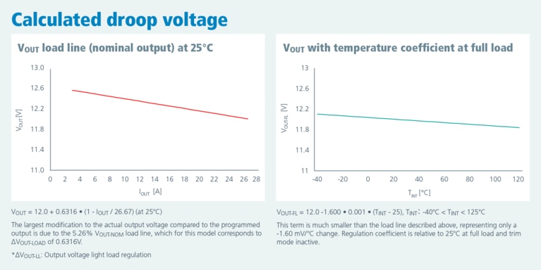
在滿載(IOUT = 26.67A)和 25°C 條件下,該模組的標稱輸出電壓為 12V。
在恒溫條件下,DCM 呈現出 -5.26% 的負斜率負載線關係,滿載(IOUT = 26.67A)時的輸出電壓低於空載(IOUT = 0A)時的輸出。 負載線的電壓差為 0.61V(= 12V × 0.0526)。
該 DCM 內部的控制 IC 監控內部電流並調節輸出電壓。在並聯陣列運行中,電流較低的模組輸出較高的電壓,而電流較高的模組輸出的電壓較低。
此外,模組溫度的變化也會對輸出電壓產生輕微影響,進而影響均流。
如果某模組的負載高於其他模組,其相對溫度往往會上升,導致輸出電壓降低。由於其他並聯 DCM 的輸出電壓會與負載更大的 DCM 相匹配,因此它們會調整其輸出電壓以更均勻地分擔負載。
滿載條件下,DCM 在 120°C 時的輸出電壓低於 -40°C 時的輸出,-40°C 和 125°C 之間的電壓差為 0.256V。
這種下垂特性(負載線和溫度係數的綜合效應)使 DCM 模組之間無需額外的電路即可實現電流平衡。
圖 3:根據負載線和溫度係數計算下垂電壓(DCM3623)。
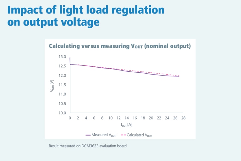
最後是對上述 VOUT 公式中的 ΔVOUT-LL 的一些補充說明。
當 DC-DC 轉換器與外部輸出負載的組合內部功耗低於每個內部 MOSFET 開關週期的最小功率傳輸時,將啟動輕負載升壓功能。 這通常發生在負載電流降至額定值的 10% 以下時。
在輕負載升壓期間,DCM 動力系統會反復開啟和關斷,從而降低開關頻率並顯著减少模組的功耗。
延長關斷時間可能會導致輸出電壓升高(見圖 4)。這種電壓升高在空載條件下最大可達 2.15V。為緩解這種電壓升高的影響,可以在輸出端添加一個泄放電阻,消耗約 10mA 的電流,從而有效降低 ΔVOUT-LL。
圖 4:輕負載調節對輸出電壓的影響。
Vicor DCM3623 採用專有的控制環路技術,能够在寬泛的輸入電壓變化範圍內實現出色的輸出電壓穩定性。此外,憑藉內寘的下垂管理功能,它能够在多個模組並聯時實現輸出自動均流,而無需附加複雜的週邊電路和通信。這樣就可以簡化電源電路的設計,並為資料中心網路交換機等需要高可靠性的系統提供穩定的供電。
本文最初由 Power Systems Design 發佈。
Yutaka Mizutani 於 2021 年加入 Vicor,擔任日本高級現場應用工程師。 他為高性能計算(HPC)、航空航太與國防、工業和汽車電源系統提供技術支援和諮詢。在加入 Vicor 前,他曾在一家電晶體供應商工作,為包括汽車、工業和消費電子產品在內的各種應用提供支援。Yutaka 擁有電氣工程學士學位和工商管理碩士學位(MBA)。
Yutaka Mitzutani,Vicor 公司現場應用工程師