
Optimizing DC-DC converter stability: AC and transient analysis in simulations of source impedance effects
Learn how to optimize DC-DC converter stability through AC analysis in the frequency-domain and transient analysis in the time-domain
By David Berry, Principal Applications Engineer
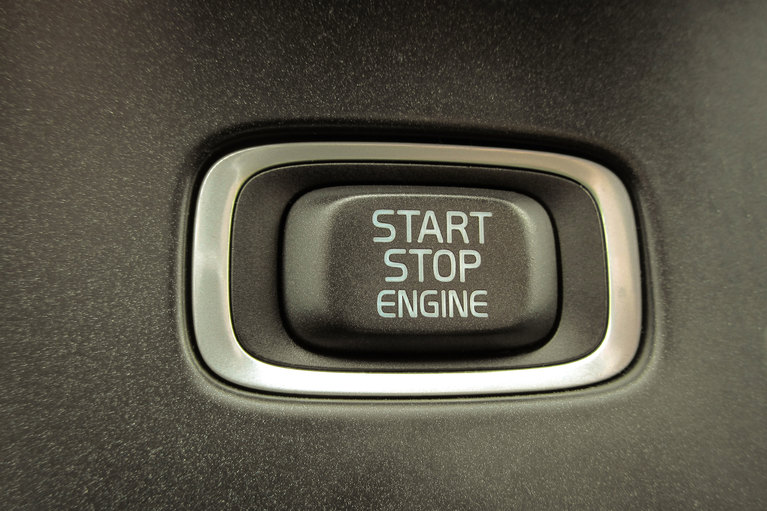
The design of isolated, regulated power systems tends to focus on performance, particularly on the ability to adapt to rapidly changing voltage demands from the load. By assuming the constant presence of source voltage, this focus neglects other factors that are becoming increasingly important. For instance, the need to provide reliable rapid (under-10ms) start up.
However, there are systems where the power source isn’t present and the system must be active within milliseconds (ms) of application of input power. These systems typically require isolation from the power source to keep grounds isolated, or create negative rails for system safety in the event of high voltage source spikes.
For example, a growing number of vehicles use start-stop engine technology to conserve fuel and battery power at traffic signals and other situations when the vehicle is stationary. In these applications, some electrical systems that would otherwise draw significant power while the vehicle idles may be shut down. However, those same systems need to be powered up again quickly and reliably. This is where rapid-start systems are essential.
Three conditions of isolated power systems warrant more careful attention since they are critical to reliable rapid-start functionality:
Control of the input dV/dt should be established with an appropriate input filter. The input section of many DC-DC converters includes an LC filter, but if this LC filter is hit with a step voltage – that is, application of DC to the power system – the LC filter can ring up to a voltage level that can damage the internal circuitry of the power component. A common specification for maximum input dV/dt is 10 volts per microsecond. Additionally, a mechanical switch or field-effect transistor (FET) that closes too quicklycan easily exceed a 10V/μs rise time. Therefore the designer should choose an input filter with current limiting to keep the input to the DC-DC converter within its input dV/dt specifications.
Input capacitance needed to ensure low source impedance and stability over line and load changes to a regulating DC-DC converter should be optimized to keep the sourcing components within their maximum ratings. Figure 1 shows the power system block diagram and Figure 2 shows the block diagram of the internals of a typical input filter. The input capacitor needs to be charged slowly to avoid exceeding the maximum dV/dt, but fast enough to achieve the <10ms start-up time of the power system. Starting at the application of system input voltage, Q1 in Figure 2 is off. At the undervoltage turn-on level the Charge Pump/Control block in Figure 2 will begin to enhance Q1 and raise the output voltage of the filter. This output voltage rise is controlled to not exceed the input dV/dt of the converter as well as control current drawn from the source.

Figure 1: Power system block diagram.

Figure 2: Internal workings of a typical input filter.
To achieve a <10ms start time the input filter on the system must charge its output capacitance as ast as possible, so the designer should select the lowest-value capacitor possible. The placement of an unregulated isolator at the output of the filter is advisable when designing for a fast turn-on time because these require little to no input capacitance and don't affect the control loop since they provide no voltage regulation.
If an isolator is used at the output of the filter and the filter output rise time is controlled, then the output of the isolator will be controlled. The isolator output mirrors the input by the voltage ratio of the converter. This will keep the downstream regulators shown in Figure 1 within their input dV/dt specification range. The regulation stage does need input capacitance for source impedance requirements and stability, so this needs to be taken into account when determining capacitance seen by the filter. The isolator will reflect its output capacitance to its input and this will be seen by the input filter.
The capacitance reflection is the isolator output/input voltage ratio squared, multiplied by the isolator output capacitance. If the output/input voltage ratio is 1/2 and the isolator’s output capacitance is 47μF, then the reflected capacitance to the filter is 1/2 squared, times 47μF or 11.75μF. The performance of the isolator is critical in this application. The isolator needs to have very little inductance as part of its powertrain. The low value for inductance enables current to flow rapidly from input to output while
maintaining a fixed input-to-output voltage ratio. Some isolators have powertrain internal inductances in the nH range.
The input filter also prevents the source from exceeding its maximum ratings, which is important for overall system reliability. The filter will shield any capacitance from high dV/dt events such as a hot plug, mechanical switch or FET switch closing. The maximum current rating of the power system source is affected by source capability, connectors and traces that go to the power supply, and these components may be weakened and turn into latent failures over time, or fail outright if subjected to current levels above their ratings. In power systems that require <10ms start up, the input voltage to the supply must come up quickly since this timing is part of the start-up sequence, but a quick start up into capacitance will result in high inrush current. The filter helps to reduce this inrush. Many filters have inrush ratings in Amps per output μF, so for a rating of 0.007A/μF paired with 47μF at the filter output, the inrush current is 0.007A*47μF or 0.329A.
Output capacitance on the power supply can create delays in rapid-start applications if it causes the converter to exceed its current limit. Overcurrent conditions cause the convert either to go through a shutdown and restart or cause a voltage drop. Both will extend the overall start-up time significantly. In many applications, the power supply will have its own output capacitance as well as load capacitance, which are charged by the output voltage of the converters. Taking this into account, it is best to design using the smallest amount of output capacitance possible. The output current charging the output capacitance is determined by the equation: I = C* dV/dt, where I is the converter output current, C is the output capacitance and dV/dt is the converter output voltage rise time. If the load is active during the rise time, then this needs to be added to the current supplied by the converter. In either case, the current should not exceed current maximum. If the current does exceed the maximum, then another converter in parallel can be added to boost the current rating of this output.
The output capacitance of the converter lowers output ripple, stabilizing the converter during operation, but by using a converter with a high switching frequency, less capacitance is required. Switching frequencies in the 500kHz to 1MHz range will allow the design to use low values of inductance and capacitance to maintain output ripple as low as 30mV to the load.
When designing a power system for <10ms start-up as shown in Figure 1, there will be several components that must become active and stay within each component’s power, voltage, and current ratings. When the system input voltage is applied, the filter controller must wake up and begin controlling the filter’s output voltage, keeping the source current below its maximum, and keeping the downstream converters within their maximum input dV/dt. When the downstream converters reach their undervoltage turn-on level, their internal controllers must wake up and effectively control their output voltages, charging the output capacitance, and in many cases the load current demand.
These wake-up times are cascaded; the resultant wake-up time has to be less than 10ms. Figure 3 shows the performance of a power system configured for a <10ms start-up time utilizing one Vicor VTM™ and two downstream Vicor PI33xx regulators. The system is configured with an isolator and two non-isolated regulators. The isolator enables the system to have a separate ground between input and output. The regulators are starting into a load of 25 watts and 33 watts, while the start time from application of input voltage is measured to be around 4ms. This system is very scalable, simply by adding power components in parallel or using components with higher power levels. Adding components in parallel also enables redundant operation.

Figure 3: A power system configured for a start-up time of less than 10ms.
Rapid start power systems present some unusual design challenges. Managing capacitance is a critical aspect of designing and deploying a flawless system. Today a growing number of applications impose frequent rapid start-up conditions on isolated power systems, which strain traditional power converters. In response, power system design must mitigate the risks caused by a rapid voltage spike and high‑current conditions caused by high input and output capacitances.
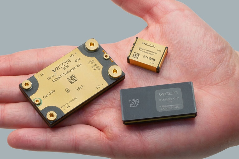
Designing an isolated power system with a less-than-10ms start-up time is achievable and reliable when using the right components. Components with high efficiency and small size are best for many applications that are mobile, in-air or on-land. Fast-acting, efficient and small power components available from Vicor provide reliable rapid-start power.
Optimizing DC-DC converter stability: AC and transient analysis in simulations of source impedance effects
Learn how to optimize DC-DC converter stability through AC analysis in the frequency-domain and transient analysis in the time-domain
Tech Taipei 2026 High Power Semiconductor Technologies Seminar
Vicor to present high density power conversion accelerating the migration to 48V power delivery networks
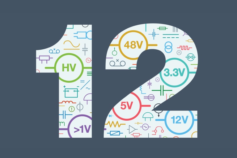
12 technical hurdles to negotiate on the road to 48V
To help you better prepare for your 48V migration consider the following 12 challenges
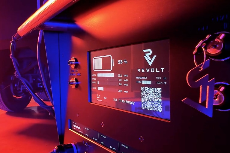
Innovating the electrification of high-voltage mobile power delivery
ReVolt is electrifying film sets! See how they use Vicor high-density power modules to swap diesel for clean, mobile energy