
The future of standardized defense platforms using MOSA, SOSA and VPX open architectures
The future of standardized defense platforms using MOSA, SOSA and VPX open architectures
Today’s commercial, industrial, retail and even domestic premises are increasingly populated by electronic devices such as PCs, monitors, servers and photocopiers which are usually powered by switched mode power supplies (SMPS). If not properly designed, these can present non-linear loads which impose harmonic currents and possibly voltages onto the mains power network. Harmonics can damage cabling and equipment within this network, as well as other equipment connected to it. Problems include overheating and fire risk, high voltages and circulating currents, equipment malfunctions and component failures, and other possible consequences. A non-linear load is liable to generate these harmonics if it has a poor power factor. Other loads can present poor power factors without creating harmonics. This post looks at these issues, the circumstances that can lead to damaging harmonic generation, and practical approaches to reducing it.
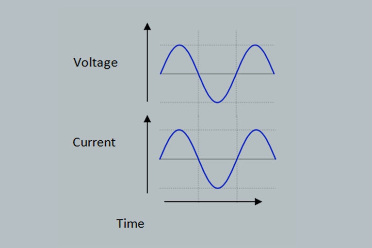
At the simplest level, we could say that an electrical or electronic device’s power factor is the ratio of the power that it draws from the mains supply and the power that it actually consumes. An ‘ideal’ device has a power factor of 1.0 and consumes all the power that it draws. It would present a load that is linear and entirely resistive: that is, one that remains constant irrespective of input voltage, and has no significant inductance or capacitance. Figure 1 shows the input waveforms that such a device would exhibit. Firstly, the current waveform is in phase with the voltage, and secondly both waveforms are sinusoidal.
In practice, some devices do have unity power factors, but many others do not. A device has a poor power factor for one of two reasons; either it draws current out of phase with the supply voltage, or it draws current in a non-sinusoidal waveform. The out of phase case, known as ‘displacement’ power factor, is typically associated with electric motors inside industrial equipment, while the non-sinusoidal case, known as ‘distortion’ power factor, is typically seen with electronic devices such as PCs, copiers and battery chargers driven by switched-mode power supplies (SMPS). We shall look briefly at the displacement power factor before moving on to the distortion case, which is of more immediate concern to electronic power system designers. However it is important to be aware of both cases. For example, some engineering courses discuss the power factor issue only in terms of motors, which causes confusion when their students later encounter poor power factor as exhibited by an SMPS.
Electric motors create powerful magnetic fields which produce a voltage, or back electromotive force, in opposition to the applied voltage. This causes the supply current to lag the applied voltage. The resulting out of phase current component cannot deliver usable power, yet it adds to the facility’s required supply capacity and electricity costs. Fitting capacitors across motors reduces the phase lag and improves their power factor.
Whereas displacement power factor loads do not cause harmonics and their associated problems, distortion power factor loads such as SMPS will do so unless their power factor is improved.
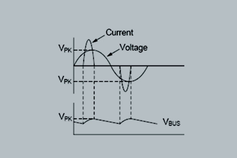
An SMPS’s AC front end typically comprises a bridge rectifier followed by a large filter capacitor. This circuit only draws current from the mains when the line voltage exceeds that across the capacitor. This causes current to flow discontinuously, resulting in the non-sinusoidal current waveform shown in Figure 2.
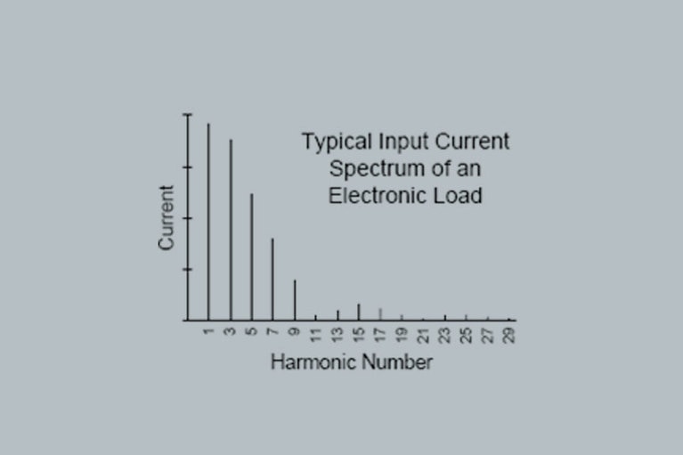
It is possible to use Fourier transforms, a mathematical process, to analyze this waveform and break it down into a set of sinusoidal components. These comprise the fundamental frequency – 50Hz in Europe, 60Hz in America – and a set of predominantly odd multiples of the fundamental, known as harmonics. The third harmonic is 150Hz (or 180Hz), the fifth, 250Hz (300Hz) and so on. Figure 3 shows a typical harmonic spectrum for an electronic SMPS load. The fundamental component is usefully consumed by the SMPS, while the harmonics are reactive and create the problems described above. The ratio of the fundamental amplitude to the sum of all the harmonic amplitudes gives the device’s power factor.
An international standard exists to describe and set acceptable limits for a product’s mains harmonics generation. Within the EU, its reference is IEC 61000-3-2, covering equipment power levels from 75W to 600W. The standard assigns equipment into four Classes – A, B, C and D. Class D covers personal computers, personal computer monitors and television receivers.
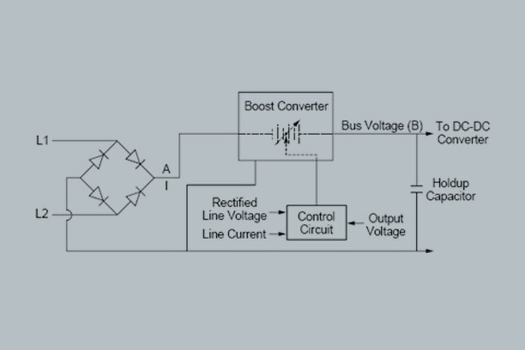
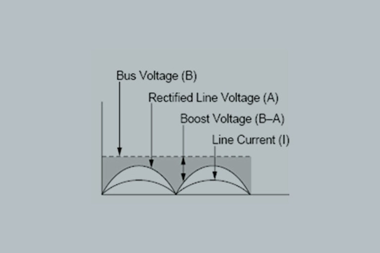
Although passive power factor solutions exist, the general industry view is that active designs offer the best power factor improvements. These are typically based on boost converter technology, as in the example shown in Figure 4.
To do so, the control circuit uses the input voltage waveform as a template. The control circuit measures the input current, compares it to the input voltage waveform, and adjusts the boost voltage to produce an input current waveform of the same shape (5–I). At the same time, the control circuit monitors the bus voltage and adjusts the boost voltage to maintain a coarsely regulated DC output (5–B). Since the primary function of the control circuit is to supply a sinusoidal input current, the DC bus voltage is allowed to vary slightly.
The use of an active power factor correcting circuit results in few discontinuities in the input current and consequently low distortion and harmonic content imposed on the input current drawn from the line. However Vicor has recently introduced a modular AC Front End, based on their new dynamic converter architecture, called Adaptive Cell.
The AC Front End offers a number of improvements for systems designers. In particular, it provides 85V to 264VAC universal input, high efficiency and high power density, especially considering that it is a complete solution including isolated and regulated DC output as well as rectification and power factor correction. The device reduces propagation of AC line harmonics, improving overall power quality at system and facility level. Total Harmonic Distortion exceeds EN61000-2-3 requirements, while high switching frequency and resonant transitions simplify external filtering and EMI standards compliance.
Product overview: AC Front End
The future of standardized defense platforms using MOSA, SOSA and VPX open architectures
The future of standardized defense platforms using MOSA, SOSA and VPX open architectures
Delivering higher power density and low noise for New Space applications
Patented power design techniques and architectures needed to deliver optimal power and low noise for space communications applications
Optimizing DC-DC converter stability: AC and transient analysis in simulations of source impedance effects
Learn how to optimize DC-DC converter stability through AC analysis in the frequency-domain and transient analysis in the time-domain
12 technical hurdles to negotiate on the road to 48V
To help you better prepare for your 48V migration consider the following 12 challenges