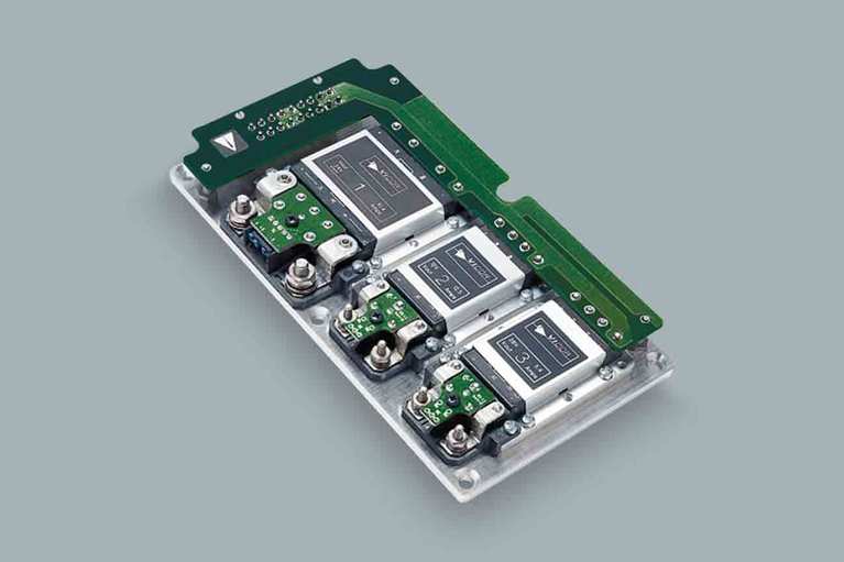
VIPAC Array™ family
VIPAC アレイ™ DC出力構成を任意に設定可能な電源システム
VIPACアレイは、柔軟性に優れたDC入力の電源システムで、薄型ののコールドプレートシャーシに最大4つのユーザーが任意に設定可能な出力を構成できます。VicorのPowerBenchコンフィギュレーションツールを使用して、電源設計者は24,28,48,72,110,150,300または375 VDCの入力で最大出力が600 W、2〜54VDCから出力電圧を選択するVIPACアレイを構成することができます。
VIPACアレイは、高電力密度で信頼性の高い分散型およびモジュール式の電源システムとして使用できます。
現在、出力電流シェアリングオプションは単一出力モデルで利用可能であり、大電力/冗長性を必要とするアプリケーションで使用できるようになります。入力コネクタおよび出力端子を使用することによりシステムの組み立てが簡単になり、汎用性の高い放熱板により放熱設計が容易になります。

パワーシステムデザイナー
特長と利点
特長と利点
Single, dual, triple & quad outputs
Fully connectorized
input & output for simplified hook up
Rugged, low-profile, coldplate chassis
High-temperature capability
コンテンツ
設計エンジニア向けコンテンツ

ReVolt cleans up Hollywood’s CO₂ emissions on sets with cleaner power
ReVolt charges up Hollywood’s clean energy ambitions with 48V and high density power modules. Portable renewable power offers cleaner, quieter power on sets
Bidirectional bridge converters tackle 12V/48VDC-power transition
Transitioning to a 48V power distribution system is more advantageous than redesigning legacy 12V designs

Power to the stars with the largest optical telescope on Earth
Microgate has developed adaptive optics technology that to help see more clearly to deep space. Learn how Vicor power modules support their mission
- Wide Range Trimming with Variable Loads
- High Efficiency Battery Charger Using Power Components
- Using Modular DC-DC Converters to Meet European Standard for Railway Applications
- Adjustable Latching Output Over Curret Circuit
- Hot Swap Capability Eliminates Down Time
- Installation Guide for the VIPAC™ Array Family of DC-DC Converters Up to 750 Watts
- Outline drawing for VIPAC Array Configuration "A"
DXF PDF - Outline drawing for VIPAC Array Configuration "B"
DXF PDF - Outline drawing for VIPAC Array Configuration "C"
DXF PDF - Outline drawing for VIPAC Array Configuration "D"
DXF PDF - Outline drawing for VIPAC Array Configuration "E"
DXF PDF - Outline drawing for VIPAC Array Configuration "F"
DXF PDF - Outline drawing for VIPAC Array Configuration "G"
DXF PDF - Outline drawing for VIPAC Array Configuration "H"
DXF PDF
- Using LugMate, 1 Output
STEP 3D PDF - Using LugMate, 2 Outputs
STEP 3D PDF - Using PlugMate, 1 Output
STEP 3D PDF - Using PlugMate, 2 Outputs
STEP 3D PDF - Using LugMate, 2 Outputs
STEP 3D PDF - Using LugMate, 3 Outputs
STEP 3D PDF - Using PlugMate, 2 Outputs
STEP 3D PDF - Using PlugMate, 3 Outputs
STEP 3D PDF - Using LugMate, 2 Outputs
STEP 3D PDF - Using LugMate, 3 Outputs
STEP 3D PDF - Using PlugMate, 2 Outputs
STEP 3D PDF - Using PlugMate, 3 Outputs
STEP 3D PDF - Using LugMate, 1 Output
STEP 3D PDF - Using PlugMate, 1 Output
STEP 3D PDF - Using LugMate, 2 Outputs
STEP 3D PDF - Using LugMate, 3 Outputs
STEP 3D PDF - Using PlugMate, 2 Outputs
STEP 3D PDF - Using PlugMate, 3 Outputs
STEP 3D PDF - Using LugMate, 2 Outputs
STEP 3D PDF - Using LugMate, 3 Outputs
STEP 3D PDF - Using LugMate, 4 Outputs
STEP 3D PDF - Using PlugMate, 2 Outputs
STEP 3D PDF - Using PlugMate, 3 Outputs
STEP 3D PDF - Using PlugMate, 4 Outputs
STEP 3D PDF - Using LugMate, 1 Output
STEP 3D PDF - Using PlugMate, 1 Output
STEP 3D PDF - Using LugMate, 1 Output
STEP 3D PDF - Using LugMate, 2 Outputs
STEP 3D PDF - Using PlugMate, 1 Output
STEP 3D PDF - Using PlugMate, 2 Outputs
STEP 3D PDF