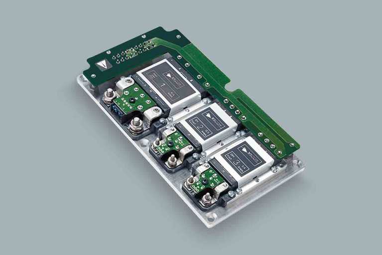
VIPAC Array™ family
VIPAC Array™ DC Configurable Power Supply
The VIPAC Array is a highly flexible system of DC input, power building blocks that can be configured with as many as four user-definable outputs on a low-profile, coldplate chassis. Using the Vicor PowerBench™ configuration tool, designers are able to specify VIPAC Arrays with inputs of 24, 28, 48, 72, 110, 150, 300 or 375VDC and outputs from 2 to 54VDC at power levels up to 600W per output. VIPAC Arrays are ideal for use in distributed and modular power systems where power density and reliable operation are critical.
A current-share option is available on single-output models enabling them to be used in applications requiring high power/redundancy. Fully connectorized input and output terminations speed system installation and a versatile coldplate chassis simplifies thermal management.

Power System Designer
Features and Benefits
Features and benefits
Single, dual, triple & quad outputs
Fully connectorized
input & output for simplified hook up
Rugged, low-profile, coldplate chassis
High-temperature capability
Resources
Resources for the design engineer

ReVolt’s carbon-free power platform electrifies movie sets
Film production sets are getting more electrically intensive, and using gensets can lead to engineering constraints and environmental problems

Hollywood goes clean energy: Vicor power modules power movie sets with ReVolt
ReVolt has developed a better way to power film sets and studio exteriors by providing clean, mobile, and always-on electricity

Q&A: Vicor powers next-gen active suspension system
Electric vehicles evolve to support higher performance, reduced weight, and improved ride dynamics, power system design is being pushed to new limits
- cURus – UL 60950-1, CSA 60950-1
- cTÜVus – EN 60950-1, UL 60950-1, CSA 60950-1
- CE Mark – Low Voltage Directive (2014/35/EU)
- CE Mark – Low Voltage Directive (2014/35/EU) and RoHS Recast Directive (2011/65/EU)
- CB Certificate – IEC 60950-1
- Outline drawing for VIPAC Array Configuration "A"
DXF PDF - Outline drawing for VIPAC Array Configuration "B"
DXF PDF - Outline drawing for VIPAC Array Configuration "C"
DXF PDF - Outline drawing for VIPAC Array Configuration "D"
DXF PDF - Outline drawing for VIPAC Array Configuration "E"
DXF PDF - Outline drawing for VIPAC Array Configuration "F"
DXF PDF - Outline drawing for VIPAC Array Configuration "G"
DXF PDF - Outline drawing for VIPAC Array Configuration "H"
DXF PDF
- Using LugMate, 1 Output
STEP 3D PDF - Using LugMate, 2 Outputs
STEP 3D PDF - Using PlugMate, 1 Output
STEP 3D PDF - Using PlugMate, 2 Outputs
STEP 3D PDF - Using LugMate, 2 Outputs
STEP 3D PDF - Using LugMate, 3 Outputs
STEP 3D PDF - Using PlugMate, 2 Outputs
STEP 3D PDF - Using PlugMate, 3 Outputs
STEP 3D PDF - Using LugMate, 2 Outputs
STEP 3D PDF - Using LugMate, 3 Outputs
STEP 3D PDF - Using PlugMate, 2 Outputs
STEP 3D PDF - Using PlugMate, 3 Outputs
STEP 3D PDF - Using LugMate, 1 Output
STEP 3D PDF - Using PlugMate, 1 Output
STEP 3D PDF - Using LugMate, 2 Outputs
STEP 3D PDF - Using LugMate, 3 Outputs
STEP 3D PDF - Using PlugMate, 2 Outputs
STEP 3D PDF - Using PlugMate, 3 Outputs
STEP 3D PDF - Using LugMate, 2 Outputs
STEP 3D PDF - Using LugMate, 3 Outputs
STEP 3D PDF - Using LugMate, 4 Outputs
STEP 3D PDF - Using PlugMate, 2 Outputs
STEP 3D PDF - Using PlugMate, 3 Outputs
STEP 3D PDF - Using PlugMate, 4 Outputs
STEP 3D PDF - Using LugMate, 1 Output
STEP 3D PDF - Using PlugMate, 1 Output
STEP 3D PDF - Using LugMate, 1 Output
STEP 3D PDF - Using LugMate, 2 Outputs
STEP 3D PDF - Using PlugMate, 1 Output
STEP 3D PDF - Using PlugMate, 2 Outputs
STEP 3D PDF
Promo Component
Related Products
Related Products

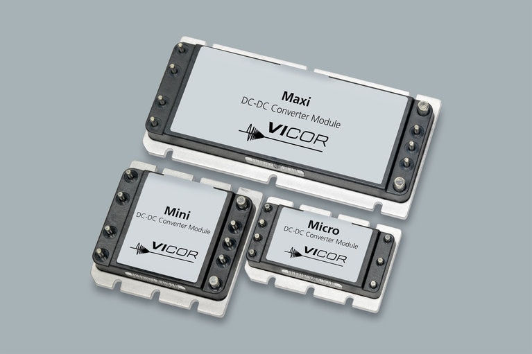
The DC-DC converter that established the “brick” standard