
Achieving seamless interoperability and long-term upgradeability
Understand which specifications to look for and what tradeoffs will be acceptable, to choose products that best fit your design requirements
By Joe Ares, Senior Principal Engineer
This white paper investigates the optimization of DC-DC converter stability through AC analysis in the frequency-domain and transient analysis in the time-domain. While frequency-domain methods like the Middlebrook criterion effectively assess impedance interactions, they fall short of capturing nonlinear dynamics and constant-power load instabilities under transient conditions.
Time-domain transient analysis bridges this gap by simulating real-world performance during transients, aiding in the selection of filter component values. By using both AC analysis in the frequency-domain and transient analysis in the time-domain simulation strategies, engineers will have the tools to minimize design iterations and enhance stability in their designs.
Source impedance plays a critical role in determining system stability and performance when designing with DC-DC converters. Variations in source impedance arising from input filters, cabling or power distribution networks can interact with the converter’s input dynamics, potentially leading to instability, oscillations or degraded transient response. Understanding and mitigating these effects is essential for ensuring reliable operation in applications ranging from aerospace to consumer electronics.
Frequency-domain AC analysis provides valuable insight into stability margins and steady-state behavior via small-signal models like Bode plots and impedance overlap techniques. However, these methods rely on linearized approximations, which may overlook nonlinear dynamics or transient events prevalent in real-world operation. Another approach is needed to complete the picture: time-domain analysis, particularly transient analysis, captures large-signal behavior, transient responses and nonlinear interactions under varying conditions. Engineers can therefore achieve a comprehensive understanding of stability by using simulation tools to conduct AC and transient analysis, ensuring robust designs that perform reliably in a wide range of likely real-world scenarios. This white paper examines the impact of source impedance on DC-DC converter stability, contrasts frequency-domain and time-domain methodologies and highlights the benefits of transient analysis for optimizing performance.
AC analysis simulations of source impedance focus on evaluating the interaction between the DC-DC converter’s input impedance and the source impedance, using frequency-domain techniques like Bode plots. The Middlebrook stability criterion, which assesses stability by ensuring the ratio of source impedance to converter in-put impedance remains below unity, provides a critical framework to prevent oscillations. This approach identifies instability risks at frequencies where source and converter impedances are closely matched.
In transient analysis, a constant-power load (CPL) closely mimics the behavior of a downstream DC-DC converter, as both exhibit negative incremental impedance characteristics. A CPL maintains constant power by decreasing its input current as input voltage in-creases (and vice versa), mirroring the input dynamics of a tightly regulated DC-DC converter, which adjusts its current draw to maintain constant output power. Both CPLs and DC-DC converters can destabilize the power system due to their negative impedance, potentially causing oscillations or instability.
However, CPLs oversimplify the complex behavior of actual converters, which include nonlinear control loops, switching harmonics and mode-dependent impedance variations (e.g., continuous vs. discontinuous conduction). These simplifications may lead to inaccuracies in predicting transients during start-up or fault conditions, where the converter’s behavior deviates from a perfect CPL. Moreover, CPLs fail to capture beat frequencies arising from parallel converters with unsynchronized switching frequencies, as noted in the Vicor DCM™ Design Guide’s discussion of parallel operation.
Despite these drawbacks, a CPL is often sufficient for time-domain transient analysis, as it captures the dominant destabilizing effect—negative impedance—while remaining computationally efficient. It allows engineers to analyze worst-case stability scenarios such as load steps or voltage transients and design robust input filters or control strategies without needing a detailed model of the downstream converter. For many applications, especially in early design stages or system-level analysis, the CPL’s simplicity and ability to replicate primary dynamic interactions make it a practical and effective tool, balancing accuracy with simulation speed and ease of implementation.
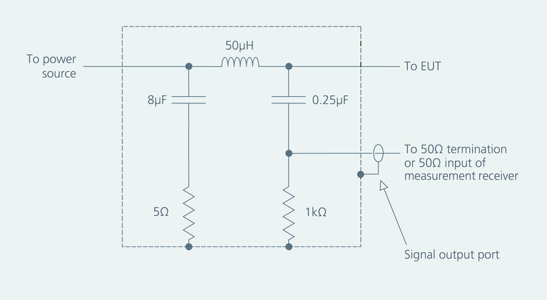
In MIL-STD-461 EMI testing, the Line Impedance Stabilization Net-work (LISN) shown in Figure 1 introduces a standardized impedance, typically 50µH in series with 5Ω for specific frequency ranges, ensuring repeatable EMI measurements. This impedance interacts with the DC-DC converter’s input filter and control loop, potentially altering conducted emissions and stability margins or inducing oscillations if the impedances overlap at certain frequencies, as analyzed in frequency-domain AC analysis. Unlike the variable source impedance encountered in real-world systems, such as batteries or power buses, the LISN’s fixed impedance may mask or exaggerate issues that manifest in actual operation. While LISN-based testing verifies compliance with EMI standards, these interactions necessitate additional AC analysis or transient analysis to ensure converter performance and stability in practical applications, particularly when transitioning from test conditions to real-world environments.
Figure 1: The standard LISN indicated by MIL-STD-461 for EMI testing shown above provides a fixed impedance, which may either mask or exaggerate stability issues. Additional AC and transient analysis is therefore needed to get a more accurate understanding of system stability with variable source impedance.
The Middlebrook stability criterion requires that the source impedance, including the converter’s internal capacitance, remain significantly lower than the converter input impedance in frequency-do-main AC analysis. A common design target is a source impedance at least ten times lower (20dB separation), but for low-voltage, high-power designs, this can necessitate impractically large capacitors.
In these cases, a minimum of two times lower (6dB separation) may suffice, balancing stability with practical component sizing. To verify the stability of the DC-DC converter DCM3623T50M31C2M00 in the presence of a LISN, the AC analysis schematic shown in Figures 4, 5 and 6 as well as the impedance plots shown in Figure 7 illustrate three scenarios:
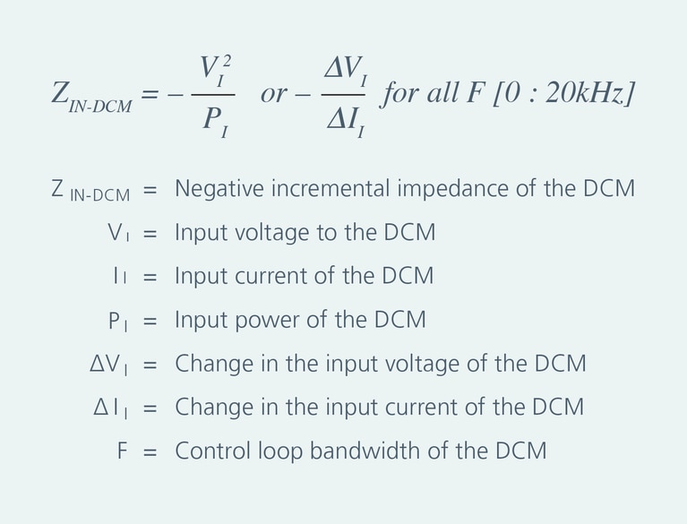
The simulations also incorporate the LISN impedance, the converter’s internal input capacitance and the converter input impedance, calculated using the formula provided in the Vicor DCM Design Guide shown in Figure 2.
Figure 2: Formula to simulate the input impedance of the DCM.
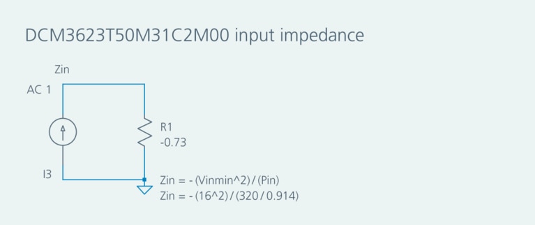
Figure 3: Simulation schematics for the input impedance.
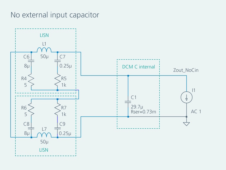
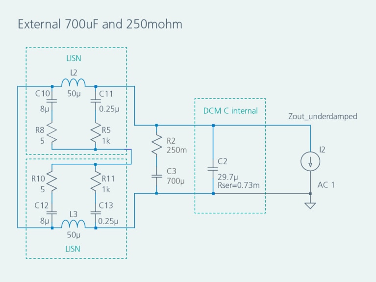
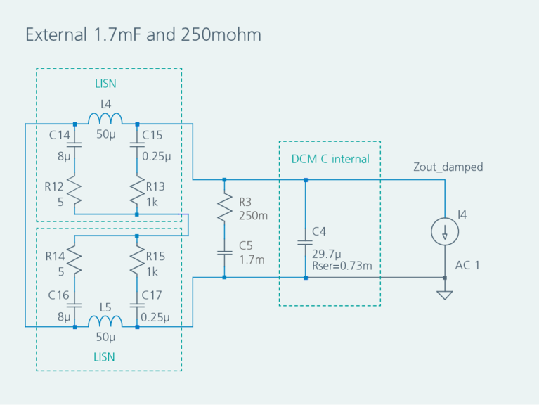
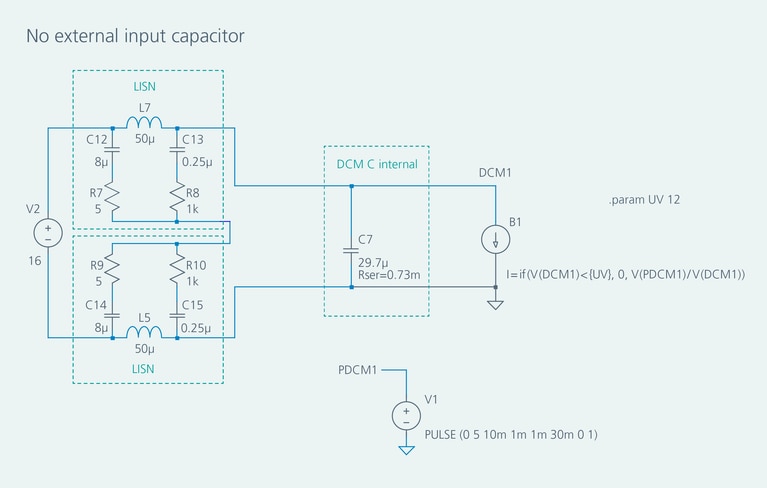
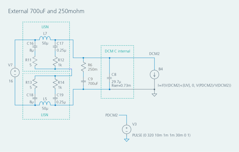
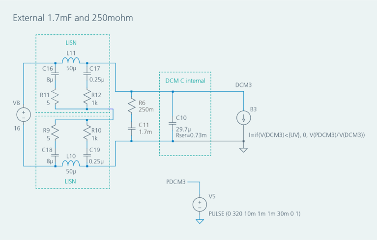
The simulation schematics for AC analysis of a Vicor DCM3623T-50M31C2M00 with LISN enable comparison of different source impedance scenarios. Figures 4, 5 and 6 show the simulation schematics for the input impedance with no external input capacitor (Figure 4), with a 700µF external capacitor with 250mΩ damping resistor and no impedance separation (Figure 5) and with 250mΩ damping resistor and 6dB impedance separation (Figure 6).
Figure 4: Simulation schematics for the input impedance with no external input capacitor at all.
Figure 5: Simulation schematics for the input impedance with a 700µF external capacitor with 250mΩ damping resistor and no impedance separation.
Figure 6: Vicor DC-DC converters combine high bandwidths with soft switching topologies to solve challenges associated with ripple rejection in EVs more effectively than conventional solutions.
The AC analysis of each of the three scenarios presented in Figures 3, 4, 5 and 6 illustrate how the use of different input capacitance values impact source impedance overlap effects in the frequency domain. Figure 7 clearly shows that when there is no external input capacitance at all (scenario 1), the overlap is severe and will cause serious stability issues for the system.
Figure 7: When there is no external input capacitance at all (scenario 1), the overlap is severe and will cause serious stability issues for the system.
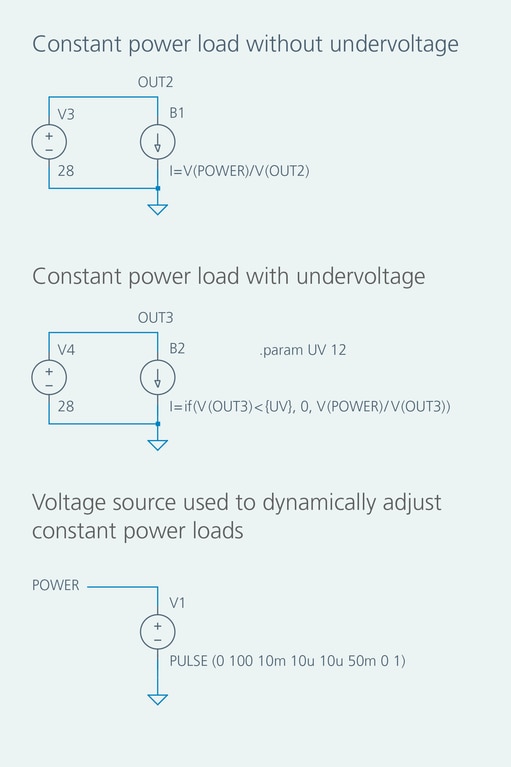
A CPL can be implemented in time-domain transient analysis using a behavioral current source, defined by the expression I = Power / (Voltage across the terminals) in LTspice®. To model dynamic loads, a voltage source can replace the fixed power value, dynamically adjusting the power and changing the expression to I = V(POWER) / (voltage across the terminals). Additionally, undervoltage can be incorporated using an “if” statement, setting the current to zero when the terminal voltage drops below a specified threshold. This enhances the simulation’s realism by mimicking converter behavior during low-voltage events. Figure 8 is an LTspice simulation schematic of CPLs B1 (without undervoltage) and B2 (with undervoltage). Voltage source V1 pulses from 0VDC to 100VDC for 50ms and represents power in the expressions for CPLs B1 and B2.
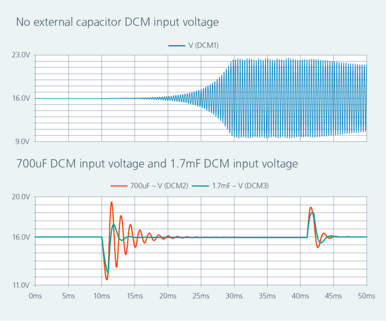
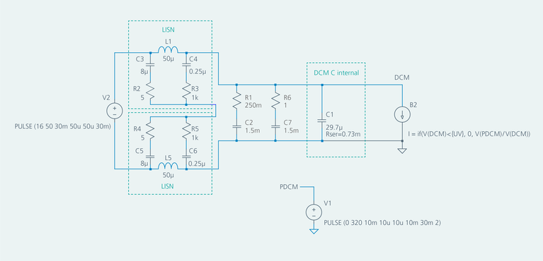
For time-domain transient analysis, a CPL simulates transient behavior with the input voltage set to 16VDC, the minimum operating voltage of the DCM3623T50M31C2M00. The simulation schematic shown in Figure 9 and plots shown in Figure 10 use the same scenarios as the frequency-domain AC analysis simulations in Figure 7. The first scenario (no external capacitor) experiences oscillations with a 5W load, demonstrating instability. Scenarios 2 and 3 (external capacitors of 700µF and 1.7mF) are subjected to 320W loads applied for 30ms with 1ms rise and fall times and demonstrate different levels of transient attenuation. Faster rise and fall times, which are realistic in practical applications, may necessitate increased capacitance or adjusted damping resistance to minimize undershoot or overshoot, ensuring robust transient response and stability under dynamic conditions.
Figure 8: CPLs using behavioral current sources B1 (without under-voltage) and B2 (with undervoltage) realistically simulate a DC-DC converter’s response to transient events.
Simulating overvoltage and undervoltage is crucial to ensure DC-DC converters can endure transient events such as load dumps, input surges and power interruptions. Time-domain transient analysis models these conditions by applying step voltage changes or transient pulses, replicating scenarios like power bus fluctuations or battery sags. In contrast, frequency-domain AC analysis, with its focus on steady-state small-signal behavior, is inadequate for these large-signal transients. Incorporating accurate parasitic models and worst-case component tolerances is thus essential to prevent overly optimistic behavioral predictions, particularly when evaluating thermal effects and interactions between the input filter and converter, ensuring compliance with standards like MIL-STD-704 or MIL-STD-461.
Choosing the correct value of damping resistors in input filters is vital for managing transients and maintaining stability, particularly in systems with DC-DC converters or high source impedance. These resistors mitigate resonant peaks that can amplify transients, causing instability or excessive overshoot and undershoot. In time-domain transient analysis, resistor values are iteratively adjusted to achieve critical damping, optimizing settling time and transient response while preserving filter efficiency. Frequency-domain AC analysis ensures the filter’s output impedance remains sufficiently lower than the converter’s input impedance, avoiding destabilizing overlap, but time-domain transient analysis offers a more comprehensive view by capturing nonlinear dynamics and large-signal effects. High power dissipation in damping resistors, driven by voltage ripple from the source or pulsed loads near the source impedance’s resonant frequencies, necessitates careful resistor sizing, often requiring pulse-withstanding resistors to handle sustained or transient power demands.
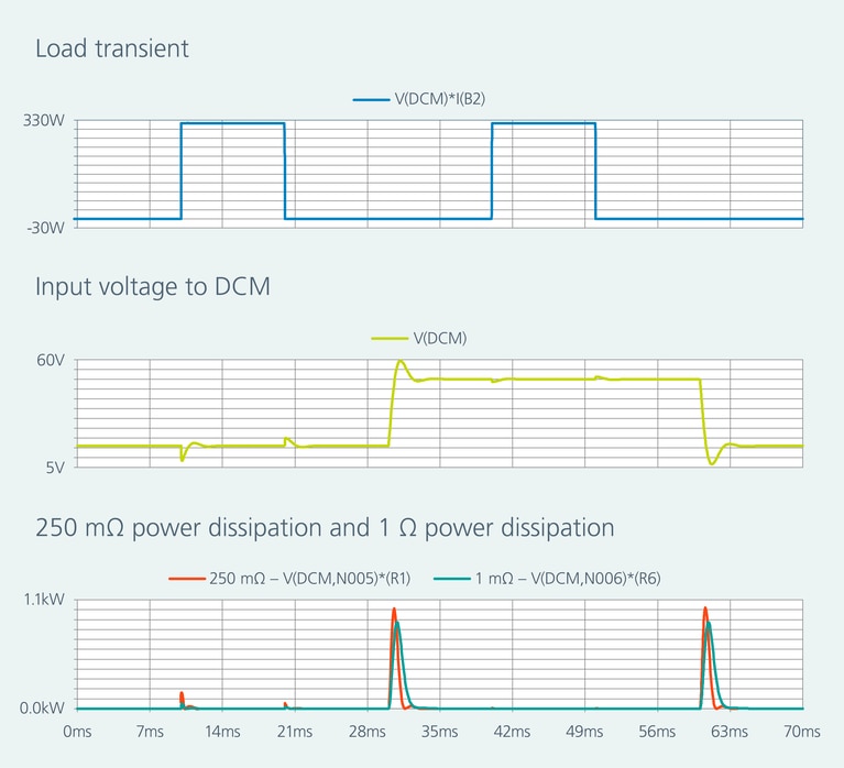
To address a 16 to 50V transient, the external input capacitance is increased beyond 1.7mF, and damping resistors are adjusted to reduce overshoot and undershoot, with a 320W CPL applied at both voltage levels. The transient analysis schematic shown in Figure 11 and plots shown in Figure 12 illustrate the transient response and power dissipation, guiding the selection of appropriately rated pulse-withstanding resistors. This ensures the filter design balances stability, efficiency and thermal performance for reliable operation under diverse transient conditions while adhering to practical component constraints.
Figure 8: CPLs using behavioral current sources B1 (without under-voltage) and B2 (with undervoltage) realistically simulate a DC-DC converter’s response to transient events.
Figure 8: CPLs using behavioral current sources B1 (without under-voltage) and B2 (with undervoltage) realistically simulate a DC-DC converter’s response to transient events.
(c)
Figures 9a – 9c: Schematics with LISN, internal and external input capacitance and CPL simulate response to a transient for the three scenarios presented in Figure 7.
Figure 10: Transient response in each of the three schematics shown in Figure 9 shows how different input capacitance choices can impact system stability with CPL.
Figure 11: Transient analysis schematic of minimum and maximum input voltage steps with load transient employs higher input capacitance and pulse-withstanding damping resistors to model DC-DC converter stability when confronted with power bus fluctuation.
Figure 12: Simulated transient performance of voltage step, load step and damping resistor power dissipation using the schematics in Figure 11 allows the system designer to balance system stability, efficiency and power dissipation when choosing appropriate damping resistors.
Vicor DC-DC converters leverage zero-voltage switching (ZVS), zero-current switching (ZCS) and high-frequency operation to enhance filter design efficiency. These technologies minimize switching losses and electromagnetic interference (EMI), enabling the use of smaller, more compact input and output filters com-pared to traditional pulse-width modulation (PWM)-based converters. The high switching frequency, typically in the megahertz range, reduces the size of filter components like capacitors and inductors needed to meet EMI requirements. This results in a more space-efficient power delivery network, which is particularly advantageous in aerospace applications where size and weight are critical constraints.
The analysis of source impedance effects on DC-DC converter stability highlights the importance of integrating frequency-domain AC analysis and time-domain transient analysis to deliver robust, reliable performance across demanding operating conditions. By combining AC analysis, which leverages the Middlebrook stability criterion to ensure impedance separation, with transient analysis, which captures nonlinear dynamics of constant power loads and transient events, engineers can comprehensively address stability challenges posed by source impedance, in-put filters and real-world power distribution networks. Strategic optimization of the filter components mitigates resonant peaks and transient-induced oscillations, balancing stability, efficiency and thermal performance.
This dual-domain approach empowers engineers to design DC-DC converters with filters that exceed stringent standards, such as MIL-STD-461 and MIL-STD-704, preventing catastrophic failures in mission-critical applications from high-power aerospace systems to compact consumer electronics. By adopting this methodology, designers can minimize costly iterations, enhance system reliability and confidently meet the evolving demands of modern power electronics.
Achieving seamless interoperability and long-term upgradeability
Understand which specifications to look for and what tradeoffs will be acceptable, to choose products that best fit your design requirements
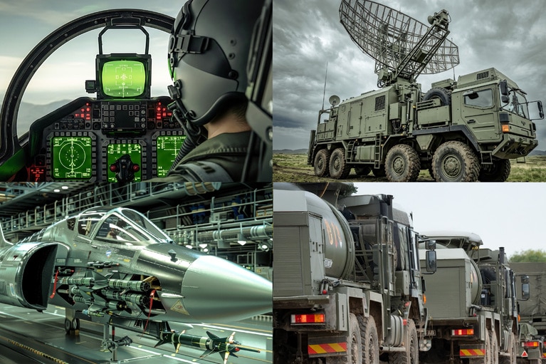
Quickly modifying a standard SOSA supply to meet an applications hold-up requirements for vehicle protection and countermeasures
Learn how Vicor delivers power to vehicle protection and countermeasures systems using a configured SOSA aligned power supply
Adjusting one of the VITA supply voltage outputs easily and quickly for ground mobile radar
Learn how Vicor delivers power to ground mobile radar using time- and cost-effective Vicor VPX solutions
High reliability VITA 62 supply that handles unique current requirements for aircraft radar
Learn how Vicor delivers power to aircraft radar using high power and high current delivery of Vicor VPX products