
The future of standardized defense platforms using MOSA, SOSA and VPX open architectures
The future of standardized defense platforms using MOSA, SOSA and VPX open architectures
Radiation-tolerant design requirements restrict the selection of components. The addition of performance monitors, safety protection mechanisms, power disconnects and reset circuitry must not exceed the efficiency, size and weight requirements of the final solution.
By Salah Ben Doua, Principle Applications Engineer and Ken Coffman, Senior Field Applications Engineer
Electronic systems in space are exposed to many hazards. Among other things, without the Earth’s protective magnetic field deflecting particles and our atmospheric blanket absorbing solar and cosmic rays, systems are exposed to greater levels of wave and particle radiation. Semiconductor devices are particularly vulnerable to particle radiation, which can lead to component or system faults or failures.
But even passives can be problematic because of issues such as outgassing. Thermal management is more challenging too because convection cooling does not work in space, so designers are limited to removal of heat through conduction to a radiating surface.
This article explores these issues as they relate specifically to the design of space power systems. The focus here is narrowed even further to those “new space” applications where “radiation tolerant” components and circuitry are required rather than the more robust “radiation hardened” devices and circuits. The radiation-tolerant requirement sets the bar lower in terms of a component or circuit’s ability to withstand space radiation as reflected, for example, in a component’s lower rating for total ionizing dose (TID). However, in exchange for this reduced degree of radiation robustness, component cost is also expected to be lower.
While semiconductor device selection is at the heart of developing radiation-tolerant power systems, it is just one of many design strategies that can be deployed at the component and circuit levels. This article discusses the basic strategies as well as the multiple benefits of soft switching in radiation-tolerant power systems.
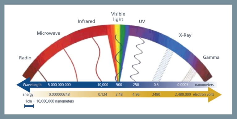
For our purposes, wave radiation includes rays and electromagnetic waves. Intuition about wave radiation is guided by what our senses can detect, i.e. visible light we experience with our eyes, infrared light we experience as heat and ultraviolet light we experience when it sunburns our skin.
Generally, wave radiation has properties similar to optics including reflection, absorption, refraction and diffusion. However, space (wave) radiation wavelengths extend above and below the visible light spectrum. Radiation below visibility includes microwaves and radio frequencies (RF). Radiation above visibility includes ultraviolet, X and gamma rays. In Figure 1, note the wavelengths and associated energies—which are key parameters for measuring radiation exposure.
Wave and particle radiation are not really two separate things, but the effects on electronic systems are different. Individual particles have very little mass, but can be accelerated to very high velocities. They can also carry charges—generally positive when negative-charge electrons are stripped from atomic orbits.
From particle radiation, we see physical damage, particularly to semiconductor crystal lattices—damage that is permanent and/or cumulative. We can see temporary upsets where electrons are dragged into depletion regions and make a nonconducting region conduct. We can also see permanent damage when positive ions replace doping atoms in a crystal matrix—sometimes making a semiconductor conduct when or where it shouldn’t can also cause permanent damage via circuit malfunction.
There are many hazards in space. Much of radiation damage is cumulative, so the length of the mission is a factor. The intensity of radiation increases as the electronics exit the earth’s system, so orbit or exposure to deep space are also factors.
An added factor in the vacuum of space is that the useful convection we use for terrestrial cooling does not work. Conduction works for spreading thermal energy, but eventually, excess heat must be radiated into cold space. A complicating factor is that surfaces exposed to the sun will get very hot, something like 250˚F (120˚C) while shaded surfaces will be very cold, around –238˚F (–150˚C). The thermal design of a satellite system is complex.
Figure 1: Radiation spectrum (iIllustration courtesy of Harvard University)[1].
Even in today’s fast-paced new space business environment, costs to launch and to replace dead satellites are substantial, so care in design is important. We really want the highest reliability we can afford.
How is this done?
There is no one answer—solutions for creating robust space electronic systems are multifaceted.
Regardless of design strategies and power supply topologies, space electronic systems must be analyzed, simulated and tested for environmental and radiation performance.
Radiation-tolerant design requirements restrict the selection of components. The addition of performance monitors, safety protection mechanisms, power disconnects and reset circuitry must not exceed the efficiency, size and weight requirements of the final solution.
Balancing design tradeoffs by choosing an appropriate power system architecture is important. Topology and switching modes like soft switching (versus hard-switched power converters) can make a system less sensitive to parasitic effects like ringing—ringing that increases voltage stress on switching components.
As one example of the importance of topology selection in a new space design, the switching mode affects all the key specifications of power-conversion implementations including power density, efficiency, transient response, output ripple, electromagnetic interference (EMI) emissions and cost.
Dominant switching-loss terms are attributable to the turn-on behavior of a power train’s high-side MOSFET via gate-charge requirements and drain-to-source capacitance. Switching losses increase with, and thus limit, switching frequency. Body-diode conduction losses detract further from power-conversion efficiency in hard-switched converters. Though GaN FETs do not have a physical body diode, they do have a reverse conduction mode clamping at several volts. This makes the GaN dead-time conduction period very challenging to manage.
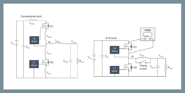
In a synchronous, hard-switched buck topology, the high-side FET turns on when it has the maximum voltage across it (see Figure 2a) and it conducts its maximum current during the turn-on portion of the operating cycle. Power losses in the high-side switch, therefore, are at a maximum during the off-to-on transition. The larger the input voltage, the higher the power loss, so converters in high voltage-ratio applications (e.g., 28V to 3.3V) tend to deliver poorer efficiency than the same converters in circuits demanding lower conversion ratios (e.g., 5V to 2.5V).
Figure 2: Conventional, hard-switched buck converter (a) versus zero-voltage switched (ZVS) buck converter. (Illustrations courtesy of Electronic Design, Stephen Oliver)[2].
The alternative, soft switching, significantly reduces these switching losses. Soft-switching techniques require more complex control circuits because the switch timing must be coordinated with the switched waveform.
One example of soft switching is the ZVS (zero-voltage switching) technique, which improves conversion efficiency across a range of power topologies. As the name suggests, ZVS switches the high-side FET on when the voltage across the switch is at or near zero (see Fig. 2b). This breaks the link between power losses and the voltage conversion ratio during the high-side FET’s turn-on interval.
Operation of a clamp switch with the ZVS technique allows the converter to store a small amount of energy in the output inductor when both high-side and low-side switches are off. The converter uses this otherwise-wasted energy to discharge the high-side FET’s output capacitance and charge the synchronous FET’s output parasitic.
Taking the FET’s output capacitance out of the switch’s turn-on behavior desensitizes FET selection with regard to CGD and, consequently, allows designers to focus on on-state channel resistance instead of traditional figures of merit such as the product of channel resistance and gate capacitance.
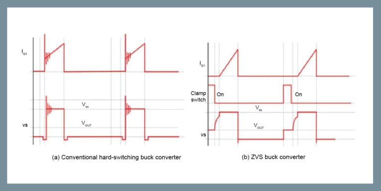
This method of driving the high-side FET during turn-on avoids exciting the switch’s parasitic inductance and capacitance, which tend to resonate, inducing large voltage spikes and ringing in hard-switched topologies (see Figure 3a). By eliminating the spikes and preventing the ringing (see Figure 3b), ZVS removes another power-loss term and eliminates a source of EMI emission.
Eliminating the voltage spikes from the switching behavior also allows designers to select lower-voltage FETs with lower RDSON improving the efficiency.
Figure 3: Hard-switching versus soft-switching waveforms (illustration courtesy of Electronic Design)[2].
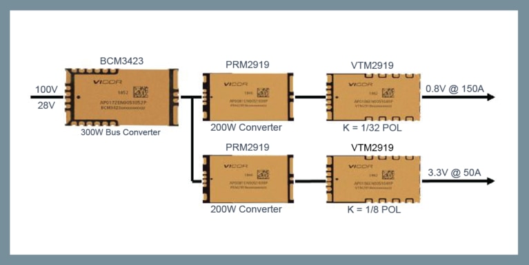
Soft switching is extremely versatile. For example, Vicor uses soft-switching techniques in its radiation-tolerant power module solutions for powering high-performance communication ASICs (see Figure 4) dedicated to MEO and LEO satellite applications. The system modules use ZVS buck-boost topology for the PRM™ and ZVS and ZCS Sine Amplitude Converters (SACs) for both the BCM® and the VTM™.
The small size of the VTM allows it to be placed as close as possible to the ASIC. Optimizing the power distribution network (PDN) is very critical when dealing with high currents consumed by modern ASICs, FPGAs, CPUs and GPUs. Vicor modules combine soft-switching solutions, rad-tolerant active components and automotive-qualified passive components.
To mitigate the SEFI (single event function interrupt), all radiation-tolerant modules include completely redundant power trains operating in parallel. If one power train gets upset due to a single event, its protection circuits force a power-off-reset. During the reset interval, the redundant power train carries the full load and after the reset both power trains operate in parallel again.
Figure 4: High-power resonant (ZVS and ZCS) topology modules.
This article was originally published by How2Power.
Salah Ben Doua, Principle Applications Engineer, has 30 years of experience in the field of power design and has been supporting Vicor customers for over 20 years, providing expertise and advice in the development of dc-dc and ac-dc power systems in a multitude of areas, including aerospace and defense, industrial, rail, lighting and communications. Salah received a Ph.D. from the National Polytechnic Institute of Toulouse, specializing in power conversion.
Salah Ben Doua, Principle Applications Engineer
Ken Coffman, Senior Field Applications Engineer, is assigned to Vicor’s New Space Initiative. He is located in Phoenix, Arizona. You can email Ken at kcoffman@vicr.com.
Ken Coffman, Senior Field Applications Engineer
The future of standardized defense platforms using MOSA, SOSA and VPX open architectures
The future of standardized defense platforms using MOSA, SOSA and VPX open architectures
Delivering higher power density and low noise for New Space applications
Patented power design techniques and architectures needed to deliver optimal power and low noise for space communications applications
AI for space applications
AI has the potential to change our world with applications delivering real impact. Learn how Spacechips is powering the next generation of AI in space
Spacechips high current transponder powers on-orbit AI-driven communication
Smaller satellites with sophisticated computational capabilities is in demand. Learn how low-noise, AI-enabled power is driving creative new applications