From central power to distributed power architecture in ATE
Automated Test Equipment (ATE) historically has been built with a centralized power architecture. Silver boxes provided a limited number of standardized voltage supplies, which were then routed to individual test cards. This arrangement was effective and convenient, as instrument card circuits did not require significant power levels: most voltages were linearly regulated from the closest available supply voltage, which was routed to each card from the centralized silver-box power supply. Moreover, early DC-DC converters were expensive, bulky, noisy and unfamiliar to power designers.
As instrumentation card requirements grew in terms of count and diversification of channels and loads, distributed power architectures became a necessary choice. A simpler, central “bulk” power device supplied a single regulated higher DC voltage, typically 48V, to a backplane distribution system. Test cards devoted some of their area to DC-DC converters, typically on their periphery, whose outputs closely matched the measurement circuits’ needs.
Figure 1: Progression of ATE power distribution architectures over time.
Test circuitry today requires more power to operate and voltage/current requirements span a wide range. At the same time, test instrumentation requires not just power, but also the ability to accurately and quickly modulate various voltage rails in order to completely characterize a DUT’s analog partitions. The power system becomes a key portion of the ATE, driven by increasing performance and density of VLSI or SOC state-of-the-art designs.
The “higher-density,” “higher-dynamic” trend also is challenging at voltages in the 48V range, as higher current requires larger copper-cross section within densely populated boards. Some new concepts are being explored today, including Factorized Power Architecture™ and 400VDC distribution.
Next, we’ll analyze how instrumentation cards and DUTs requirements affect the power distribution architecture within an ATE system and the main design parameters that need to be considered to optimize the distribution network within an ATE rack, among various instrumentation cards and up to the measurement circuitry.
Power distribution network design considerations
As mentioned in the previous paragraph and shown in Figure 1, central power has been abandoned for quite some time and distributed power with backplane distribution approach is standard practice today. The telecom and datacom industries have been using this approach for a long time and in many aspects face the same challenges as a modern ATE. Actually, a good portion of the silicon chips that ATEs need to verify and characterize are implemented in telecommunication systems, computing and routing systems that the telecom industry utilizes to move ever-increasing volumes of wired and wireless data around the world. The most striking similarity between the two “worlds” is the need for dense and granular power systems, although with different objectives: throughput and flexibility for ATEs, total cost of ownership (TCO) for telecom and datacom systems.
Bill of materials
Objective: To minimize bill of materials.
Power distribution bill of materials are directly affected by one main parameter: backplane distribution voltage. The simple consideration of distribution losses should drive the tradeoff in choosing copper cross section. The primary concern for ATEs would be avoiding thermal management issues; therefore, distribution losses should be maintained within a range easily manageable by the existing cooling system. Moreover, if instrument cards need to be hot-plugged, appropriate ORing devices should be installed on each card. The list below provides a guideline derived from telecom data center studies.
Backplane or intermediate distribution DC voltage:
- 12V with up to 5kW of optimal power range
- 48V with 4 – 80kW of optimal power range
- 380V with greater than 80kW of optimal power range
While ATEs requiring more than 20kW are restricted to ATE supporting high degrees of parallel test, it is clear that 48V backplanes may no longer be the best choice and 400V backplanes with their lower currents are waiting to be exploited once 48V will no longer suffice.
Operating costs, efficiency and losses, thermal management
Objective: To optimize the thermal management system by controlling distribution losses.
Until this point we have focused on backplane distribution. While the management of thermals on the backplane is usually not very difficult, the instrument’s card power system can be quite challenging to control. Moreover, power buses on instrument cards take up “precious real estate” from the card itself. The most logical choice is therefore to distribute the backplane voltage on the card as close as possible to the actual load, which might be either the measurement circuitry or an onboard DC-DC converter. Obviously, if a low-voltage backplane is used – for example, 12V – the copper in the PCB would need to be not only properly sized, but also appropriately cooled.
A less obvious aspect is the difficult to accurately compensate for DC (I2R) and AC (L • di/dt) drops as current levels increase. Designers might need to oversize the converter’s powertrains as well as add filtering and decoupling networks as power distribution voltages fall below 48V.
Operating costs, efficiency and losses, thermal management
Objective: Enabling the highest degree of flexibility in test card design and configuration.
Instrument cards have an ever-increasing spectrum of loads to supply. Therefore, power systems with granular components provide significant advantages to the designer. An effective approach consists of adopting an intermediate bus architecture, where the backplane voltage is effectively reduced to a lower, “intermediate” bus voltage, then regulated via a standard synchronous-buck, point-of-load converter.
Within the flexibility paradigm, reuse of a design has become a common choice to leverage standardization within a diverse power system. Designers can “source and tailor” a multiplicity of regulators from a set of valid designs to electrically fit the specific loads and place them as close as possible to the load themselves to maximize dynamic performance. Clusters of regulators would be supplied by a single intermediate bus and sustained by a bus converter. While good design practice would call for matching the bus converter power throughput with the downstream regulator’s needs, constraints normally arise in effectively distributing the intermediate bus “on board.” At an intermediate bus voltage of 12V, distributing even just 300W means routing 25A, which can be challenging on high-density designs.
Figure 2: Normalized power distribution losses vs. power distribution voltage (constant copper cross section).
Reliability and redundancy
Objective: To achieve the highest degree of system availability through design for reliability and redundancy.
The power distribution network is the “spinal cord” of complex equipment, powering measurement systems and DUTs. As an ATE lifespan is usually measured in decades, identifying and controlling critical components’ mean time between failure (MTBF) is necessary. This includes:
- Appropriate electrical and thermal de-rating: While de-rating is usually perceived as a means to reduce thermal stresses, current density also can contribute to failure mechanisms. One example is electro-migration on PCB traces.
- Redundancy: Critical components whose failure jeopardizes machine availability should be made redundant and provisions made for field replacement.
Serviceability and diagnostic telemetry
Objective: To enable the highest level of modularity and provide the system with online diagnostic options over system lifecycle.
The backplane distribution approach is inherently highly flexible, allowing Hot-Swap of non-critical loads (like, for example, fans) that can be field replaced while the equipment is operating. However, the same level of flexibility should be planned on the other end of the distribution network, enabling easy access to the bulk power system.
Diagnostics also becomes a critical aspect. It is necessary to identify and isolate components or subsystem issues quickly to protect the system from propagating failures. While almost impossible in the case of central power architecture, both distributed and Factorized Power Architectures™ provide a means to automate the power distribution network diagnostic. Distributed power architecture traditionally utilizes a “margining” technique, where the remote DC-DC converter is commanded a pre-set sequence and a dedicated feedback network verifies the obtained DC or AC dynamic. Modern power components and Factorized Power Architecture provide a simpler, digital interface where supervisory controls can actually poll status information in real time via a common serial interface bus, typically I2C or UART.
Noise sources and immunity
Objective: To minimize EMC and EMI within the system, decoupling the power distribution network to minimize conducted and radiated interference.
EMC and EMI are usually perceived as the “black magic” of power design. However, a few basic rules generally apply. First, identify the noise source; and second, contain or filter the noise as close as possible to the source (assuming the noise cannot be avoided altogether). Unfortunately, the power distribution network is a good candidate for distributing conducted noise within the system as well as radiating noise around the system rack. It is therefore extremely important to implement proper filtering if not at individual DC-DC component level, at least on each instrument card to avoid crosstalk through the backplane.
A particularly insidious issue is the low-frequency noise generated on the backplane as well as intermediate buses. This is due to the input current interactions of various converters which then create low-frequency beats. Designers can try to avoid this issue by making sure that all the switching-current components are sufficiently confined within each individual converter.
Conclusion
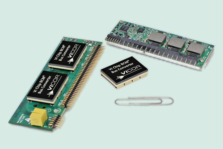
Power distribution network design is a challenge of state-of-the-art test systems. Several tradeoffs exist and need to be carefully evaluated within the power system architecture of choice. While distributed power architecture from 48V backplanes is today’s common choice, advanced architectures like Factorized Power from 400VDC distribution are becoming valuable, because they improve system density by offering higher efficiency and a higher level of granularity. Figure 3 shows an example of a standard two-stage design for point-of-load supply from 400VDC distribution: on the left, a front-end module consisting of two 400V bus converters (under the heat sinks, with a single module shown close to the paper clip); on top, a multi-phase Voltage Regulation Module (VRM) with classic 12V buck converter approach.
Figure 3: Point-of-load standard solution example from 380VDC distribution. High-voltage bus converters card (left), single 400 – 12V bus converter chip (middle, closest to paper clip) and standard multi-phase buck converter (top right).

