
High-bandwidth power modules quell the disruption of high-voltage line ripple rejection
Vicor DC-DC converters combine high bandwidths with soft switching topologies to reduce EV ripple rejection more effectively than conventional solutions
A conventional power supply or regulated DC-DC converter typically uses Remote Sense to achieve true regulation accuracy. For a system designer using, say, a brick converter the task is relatively simple; just connect the + and – Sense terminals of the brick to either side of the load, and the brick’s internal circuitry will ensure correct regulation. The sense lines allow the brick to compensate for its own output resistance, as well as the resistance of the power lines and connector pins between its output and the load. With this compensation, the correct voltage is referred to the point of load rather than the brick output terminals.
The brick, like all complete power components, will include an isolation stage; this creates design challenges as the feedback loop must also be isolated. However these issues are solved within the power unit’s design and are therefore transparent to the systems designer.
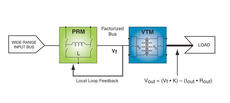
Today, however, the efficiency requirements, transient response times and competition for PCB real estate typical of today’s electronic equipment mean that many engineers are turning to more sophisticated power distribution architectures such as the Factorized Power Architecture (FPA). FPA employs integrated power components such as a PRM feeding one or two VTMs to achieve these expectations of density, efficiency and responsiveness. Figure 1 is a generic example of a PRM/VTM arrangement.
Fig.1: A simple FPA implementation with PRM and VTM
Fig.1: A simple FPA implementation with PRM and VTM
The VTM can be considered as a fixed-ratio isolated DC-DC transformer that offers high power density and efficiency, and low output impedance enabling fast transient response. The PRM provides a regulated output – a "factorized bus" – from an unregulated input source. This PRM-VTM combination creates a complete, isolated, regulated DC-DC converter.
Note that Figure 1 also shows a third wire: the Adaptive Loop connection between the PRM and VTM. This is because the ‘intelligent’ PRM handles the regulation, yet it cannot directly "see" the load for which it regulates, because the VTM with its isolation barrier lies in the way. An isolated feedback loop could be designed, but this would be a time-consuming task for systems engineers, with issues of accuracy and tolerance arising. Instead, by providing the adaptive loop feedback, the VTM acts as an eye for the PRM, communicating the information that it needs for accurate regulation.
This information relates to the resistance of the VTM’s output as well as the smaller resistance values of the power lines and connector pins between the VTM and load. In theory, these resistance values should be zero, but in practice they are not. Any such resistance will cause a voltage drop which is "stolen" from the voltage appearing across the load. The PRM can calculate the voltage drop across the VTM output terminals if it knows the current flowing through them, and their resistance, using the simple formula V = IR.
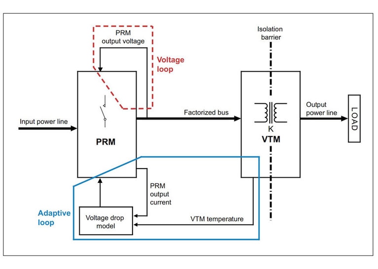
Figure 2 below shows the concept of the Adaptive Loop (AL). While the voltage loop, also shown, maintains regulation at the PRM output, the AL compensates for the voltage drops that occur from the PRM output to the actual load. The AL is centered on a voltage drop model that presents the PRM with a scaled replica of the total voltage drop in the system. The model is fed directly by current drawn from the PRM output. This can be scaled to represent the VTM’s output current by using the VTM’s K transfer ratio as the scaling factor. The VTM’s third wire feedback contains information about its output resistance, so the model can multiply this value with the scaled PRM current value to obtain the system voltage drop representation.
Fig.2: Adaptive Loop regulation conceptual diagram
Fig.2: Adaptive Loop regulation conceptual diagram
Note that the feedback link is referred to as "VTM temperature." This is because the resistance across the VTM’s output terminals will vary with temperature, so the feedback signal must accordingly also include temperature variance. Such variance is facilitated by a PTC resistor embedded within the VTM module.
The AL is a simple circuit with few components and avoids the need to transmit signals across the VTM’s isolation barrier. Reference to a more detailed Vicor application note will show that the AL includes a few resistors whose values can be calculated by systems engineers to meet the requirements of the VTM they choose. The application note includes a table of VTM part numbers and their associated output resistance and temperature coefficient values. It also provides a set of equations; these are for use in calculating the resistor values necessary to build a voltage drop model accurately matched to the VTM selected.
The application note covers half-chip as well as full-chip VTM devices. The theory provided is supported with a design example using customer boards.
Adaptive Loop control provides improved regulation over simple Local Loop control – within +/- 1% – yet requires only a simple, non-isolated, feedback connection between the VTM and PRM.
Application note: Accurate point-of-load voltage regulation using simple Adaptive Loop feedback
Product overview: PRM/VTM
High-bandwidth power modules quell the disruption of high-voltage line ripple rejection
Vicor DC-DC converters combine high bandwidths with soft switching topologies to reduce EV ripple rejection more effectively than conventional solutions
Modular approach solves 48V power architecture electrification challenges
Power dense modules from Vicor are the best way to accelerate automotive electrification. They are flexible, light weight and easy to use
The future of standardized defense platforms using MOSA, SOSA and VPX open architectures
Using open standards to increase interoperability, scalability, reliability, reduce system costs, and minimize the number of custom electronics designs
Delivering higher power density and low noise for New Space applications
Patented power design techniques and architectures needed to deliver optimal power and low noise for space communications applications