12 technical hurdles to negotiate on the road to 48V
To help you better prepare for your 48V migration consider the following 12 challenges
Density of power components has increased several orders of magnitude over the past couple of decades. On one hand this has led to a significant reduction in size and cost of power electronic converters; on the other hand, designing the appropriate cooling solution has become more and more challenging. In many cases, thermal management is the gating item that determines the feasibility of a project, and the thermal management solutions need to be evaluated at a very early stage in the design of a power supply.
To simplify your thermal evaluation Vicor has released several simulation models that enable evaluation of the thermal characteristics of our products. The simulator allows you to do a preliminary evaluation of the functionality of our products in your specific environment and operating conditions. The simulator evaluates whether the operating conditions selected by the user when under the selected cooling option are within specification, or if modification to the selected cooling strategy are needed.Overview of Vicor thermal simulator interface. In this example, the cooling type selected was “Heat Sink”. The Option of a “User Defined Cold Plate” is also available.
Overview of Vicor thermal simulator interface. In this example, the cooling type selected was “Heat Sink”. The Option of a “User Defined Cold Plate” is also available.
With just a few clicks, you can select the Vicor power component you are planning to use, customize your source and load conditions, ambient temperature, and evaluate the feasibility under several possible choices of cooling solutions. These solutions may include various types of Vicor heatsinks, as well as custom defined cold plate solutions. In a few seconds you will be able to determine the ideal cooling approach for your project, and you can proceed with your design knowing that thermal management has been addressed already!
Figure 2: Examples of results returned by the thermal simulation: the top image shows a cooling solution that is adequate for the selected operating conditions; the bottom one shows a cooling solution that is undersized, and provides directions on how to improve the thermal management.
Figure 2: Examples of results returned by the thermal simulation: the top image shows a cooling solution that is adequate for the selected operating conditions; the bottom one shows a cooling solution that is undersized, and provides directions on how to improve the thermal management.
12 technical hurdles to negotiate on the road to 48V
To help you better prepare for your 48V migration consider the following 12 challenges
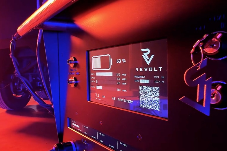
Innovating the electrification of high-voltage mobile power delivery
ReVolt is electrifying film sets! See how they use Vicor high-density power modules to swap diesel for clean, mobile energy
Why power architectures constrain New Space AI missions
Satellite AI outpaces legacy power systems. Modern compute needs sub-volt, high-amp power that traditional architectures simply can't deliver until now
Harnessing AI in space to enable faster communication and a new era of innovation
Spacechips & Vicor created the AI1 Transponder, the densest orbital AI board. FPA enables 133 TOPS for real-time satellite autonomy and 130A processing