

Accelerate your move to a high performance 48V power delivery network
This eBook provides guidance on designing 48V power delivery networks to enhance the performance, efficiency, and reliability of industrial products
When will Vicor move to WBG MOSFETs?
By Phil Davies, Corporate Vice President, Global Sales and Marketing
In 1984 I had the honor of travelling around Europe with the great Rudy Severns on a new technology teaching tour for Siliconix. I was a young applications engineer and the new technology then was the silicon power MOSFET. Engineers were using bipolar transistors in their switching power supplies, and Rudy in his “Advanced Power MOSFET Seminar” pointed out the many advantages of the silicon (Si) MOSFET, which offered higher switching frequencies and lower power losses. Rudy discussed how to use and apply them correctly and how to overcome various dV/dt failure modes when switching inductive loads.
That was over 37 years ago. Fast forward to 2021: we are in a similar place with multiple startups and large power semiconductor companies introducing new wide bandgap (WBG) gallium nitride (GaN) and silicon carbide (SiC) compound semiconductor switches to chase off the Si MOSFET, citing higher switching frequencies, lower losses and higher breakdown voltages with lower R(DS)ON. The opportunity for the new WBG MOSFETs has been created by the significant power increases in automobiles due to electrification and in data centers with the ramp in GPU-based artificial intelligence (AI) applications. In these markets, power system footprint, efficiency and weight have tremendous impact on end-system performance and value, which has escalated the importance of power system design. Even as some power design engineers begin to adopt WBG MOSFETs, advanced topologies and power architectures can still achieve higher efficiencies and power density with silicon components.
Power system design engineers are continually challenged to design a power delivery network (PDN) that takes up very little space, has the lowest weight, the highest efficiency and optimized thermal management. Achieving the best possible specifications in these areas defines a leadership product that can deliver a major competitive advantage.
Take for example battery range (distance) and fast-charging specifications for electric vehicles, or an AI supercomputer’s speed and rack power density. These are highly competitive performance specifications and must be achieved while delivering 50kW to 150kW of power. As a result, traditional power converters, regulators and their silicon components are having a very difficult time delivering the critical performance specifications for PDN size and weight.
Every system designer will ask basic questions at the beginning of any new project: Do I need to change my design from the last successful project? Can I use the same design, components and suppliers I am familiar with and have built trust with over the years? Can I just modify the design a little or does the new specification call for radical change? Are there enough advances in performance with what I know how to do, or do I need to develop a new architecture, topology or control system? How much risk can I take and will my team accept the risk in exchange for the reward in higher performance and maybe an important competitive edge?
This is no different for the power module designers at Vicor who ask these same questions in order to stay on the forefront of power module performance in terms of density, efficiency and flexibility.
One way around the power delivery challenge is to use higher voltages. Since the power term and power losses are based upon voltage levels and the square of he current (P = IV and P = I2R). By using higher voltages, PDN current levels and distribution losses in cables and connectors can be significantly reduced. This benefit has resulted in a move from 12V to 48V distribution in data center racks and mild-hybrid vehicles and 400V, 800V and 1200V battery power sources in electric vehicles. Additional benefits in PDN size and weight can be achieved by utilizing high-frequency switching topologies to reduce power converter and regulator footprints.
These challenges and large emerging-market opportunities have led to the development and now-widespread use of WBG MOSFETs, which have high-voltage capability, faster switching speed, higher temperature range, lower conduction resistance with minimum power dissipation leading to greater efficiency. These attributes are critical to achieving the required power density for many suppliers of DC-DC power supplies and power systems.
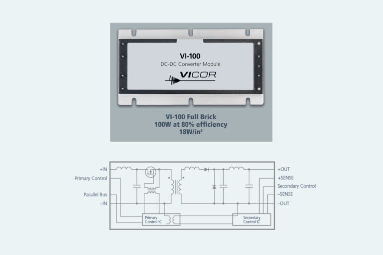
WBG MOSFETs are clearly better than Si MOSFETs for high-voltage and high-power discrete DC-DC converter designs, but at Vicor the modular power approach to power systems design and unique proprietary architectures, topologies, control systems and power packaging give longevity to the Si MOSFET. Vicor has been converting and regulating higher voltages at higher frequencies for over 40 years, with constant innovations that advance power density and efficiency. In the early 1980s, Patrizio Vinciarelli, founder and CEO of Vicor and the 2019 recipient of the IEEE Willian E. Newell Power Electronics Award, recognizing his outstanding contribution to power electronics, developed a new topology the quasiresonant forward converter with active clamp. This topology switched up to 1MHz using a frequency-modulation-based control system with zero-current switching (ZCS) and the Brick was born (Figure 1).
Figure 1: The Brick package became an industry standard form factor in the 90s. The Vicor Brick dc-dc converter uses a quasi-resonant forward converter topology and Si MOSFETs to achieve a power density of 120 W/in3 and up to 89% efficiency, depending on input voltage range and output voltage.
So, having moved to the dark side (sales and marketing) and not rememberingall of my engineering training, I asked senior applications engineer Tom Curatolo, who has been with Vicor for over 30 years, to explain some of the Brick topology and control system benefits. This is what he told me.
The Brick used Si MOSFETs and took full advantage of high-frequency switching plus the capability of synchronizing the main switch transition at zero current with a fixed on-time, significantly reducing switching losses.
Alternative hard-switching topologies trade off higher switching frequencies with system power losses. Achieving high efficiency also requires synchronous rectification and incorporating multiphase functionality. Lower frequency switching leads to larger passive components, which are required to hold the power for a longer time period between the MOSFET’s longer switching cycles based on the variable on-time.
Another tradeoff is that lower switching frequencies with chopping current during main switch transitions, results in high harmonic distortion and output ripple which needs to be filtered. This typically means adding larger input filters, which increases size and weight.
Thank you Tom! As a result of these tradeoffs, power systems based onhard-switching PWM topologies relied on Si MOSFET power switch improvements to increase power density and performance. As the power MOSFET began its journey of improvement in figures of merit (FOM) and reduction of die size vs. R(DS)ON vs. BVDSS (drainto-source breakdown voltage) to levels never dreamed of back in the 1980s, all topologies took full advantage of these power-switch improvements to reduce the size and weight of the power system.
Today, many hard-switching topologies are moving to WBG materials such as SiC and GaN power MOSFETs to make further power density and efficiency gains, especially for high-voltage and high-power systems.
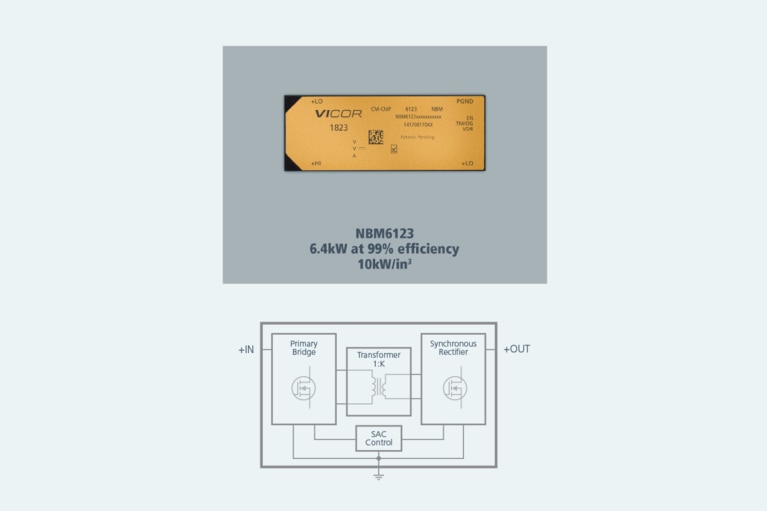
However, the Si power MOSFET still stands strong in resonant converter topologies that Vicor has invented, most notably the sine amplitude converter (SAC™) topology, with both a ZVS and ZCS control system. A clear example of the density and efficiency that can be achieved is the Vicor NBM6123, a non-isolated bidirectional 800-to-400V fixed-ratio converter, which uses the SAC topology and Si MOSFETs to achieve industry-leading specifications of power density of 10 kW/in3 with 99% efficiency (Figure 2).
Figure 2: The NBM6123, a bidirectional 800-to-400V fixed-ratio converter uses a non-isolated version of the SAC topology and Si MOSFETs to achieve a power density of 10 kW/in3 at 99% efficiency.
We are often asked: When will Vicor move to WBG MOSFETs? The answer is simple: when the merits are significant enough to justify the change. Until then, the Si power MOSFET has longevity in high-performance power modules, at least at Vicor. When Rudy Severns first championed Si power MOSFETs to replace bipolar transistors, we all knew that the day would come when a new technology would, in turn, displace it. We didn’t imagine, however, that the Si MOSFET would last for nearly four decades. The time will come when Vicor’s technology will also take WBG MOSFETs to the next level of efficiency and power density. But until then, the tried and true Si power MOSFET continues to possess longevity in high-performance power modules … at least at Vicor.
This article was originally published by IEEE Power Electronics.
Mr. Davies has served as our Corporate Vice President, Global Sales and Marketing, since February 2011. Prior to joining the Corporation, Mr. Davies was employed by the Solid State Light Engine business unit of OSRAM Sylvania as Business Creation Team Leader from September 2010 to February 2011. Mr. Davies served in various positions with Analog Devices, Inc., a manufacturer of high-performance analog, mixed signal and digital signal processing integrated circuits, most recently as Director of World Wide Business Development. Mr. Davies received a B.S.E.E. and a Masters degree in Power Electronics from the University of Glamorgan.
Phil Davies, Corporate Vice President, Global Sales and Marketing
Accelerate your move to a high performance 48V power delivery network
This eBook provides guidance on designing 48V power delivery networks to enhance the performance, efficiency, and reliability of industrial products
Build better UAVs using modular power
Power Delivery Networks (PDN) based on Vicor high performance power modules enable innovative designs for the next generation of UAV development
UAV Market Trends and Power System Seminar 2025 Taipei, Taiwan
Power modules enable top performance and innovation for today’s advanced UAVs
High-efficiency, high-density modules free up space for advanced communications and extend range
High-efficiency class of UAV depend on solar power to meet its long flight time requirements