
Accelerate your move to a high performance 48V power delivery network
This eBook provides guidance on designing 48V power delivery networks to enhance the performance, efficiency, and reliability of industrial products
By Anna Giasson and Stavros Dokopoulos
The range, productivity, and flexibility of a mobile robot can be enhanced by the optimal design of its power delivery network (PDN). There are complex power system design and architecture considerations in such PDNs due to the variation in the battery power source voltage plus the broad variety of loads that may be part of a typical system, such as high-power AI computing systems, motor drives, sensors, communication systems, logic boards and processors. There are also EMI considerations that naturally arise from developing closely-packed and dense systems that use high-power switching regulators. The result is that robotics power systems face many unique challenges and require new approaches to address them.
A modular PDN design approach, using Vicor high-density, high-performance power modules can tackle these challenges. Understanding the fundamental engineering principles and experiences from supercomputing applications to explore how the performance and design flexibility of advanced robotic power systems can be enhanced by leveraging Vicor fixed-ratio power converters and high-efficiency wide-input-range Zero-Voltage Switching (ZVS) buck or buck-boost regulators.
Two approaches to consider:
The use of fixed-ratio converters to scale the voltage of sources efficiently up or down as well as enhancing their dynamic response capabilities within the same PDN, or to adapt it to a much higher voltage source.
The various power delivery network architectures from these two power topologies provide the designer with multiple options to achieve a mobile system that meets their design goals.
When designing a power system for advanced robots, it is tempting to simply reuse a trusted DC-DC converter for each required load voltage as the need appears in form of new payloads, regardless of whether it is powering LIDAR, a GPU, a servo-drive or even constant-current loads like LED floodlights. While convenient, the evolving complexity of systems shows the need for a more holistic look at the power requirements and architecture. There are significant size, weight, performance and cost advantages to designing power systems with the latest in power converter technologies. These benefits only increase with wide-ranging load tolerances, narrow battery voltage ranges, a smaller number of isolation barriers, and in systems with short durations of maximum power and long idle times. Using newer and higher-efficiency non-isolated buck or buck-boost converters, even with input voltages above 24V, can improve overall system performance.
Fixed-ratio converters have a low-impedance path and fast transient response. The smart placement of these allows loads such as motor drives to draw current quickly without the response delay inherent in regulated DC-DC converters or the voltage droop from long low-voltage cable runs.
Both approaches enable new architectural solutions that will be explored here.
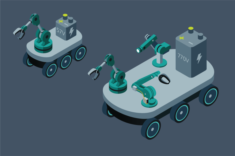
Consider two robotics platforms, their battery sources and various high-power loads as outlined in Figure 1. For the sake of simplicity, the battery is of the first comprises a 15-S LiFePO4 with a 57V float voltage, such as is used on an all-terrain last-mile delivery bot with a manipulator or other servo-drive; 57V increases energy density compared with 24V- or 48V-based systems. Imagine also being asked to mount the same or more powerful “brains and brawns” on a much larger platform, such as a self-driving truck or harvester bot with a 200-S battery featuring a 770V float voltage, or designing the latter from scratch.

Figure 1: The two robotics platforms are vastly different sizes, but their power delivery networks have much in common. A modular approach offers flexibility in the initial designs and typically faster delivery of subsequent power systems design
The load requirements include the following:
By working backwards from the load requirements, a power tree can be constructed to showing how to produce each of the needed voltages (Figure 2). This methodology enables a designer to optimize the number of regulation stages, isolation stages and transformation stages in the design. This can result in a reduction of associated losses of a needlessly complex architecture, noise, stability issues and undesirable voltage drops yielding a scalable and versatile, yet simple and efficient power solution.

Figure 2: Power delivery network of a lower-voltage supply powered by a 110VDC SELV (Safety Extra-Low Voltage) battery or a larger vehicle’s 770V battery transformed down to ~48V.
When powered from an extra-low voltage source such as a 24 or 57V battery (Figure 2), all loads are often tied to the battery negative, making isolated DC-DC converters unnecessary. A much better design would employ a modern high-voltage buck converter offering 96 – 97% efficiency with low standby power, enhancing battery life. If the input-to-output voltage ratio were to allow the buck converter to operate close to its “sweet spot” in terms of the duty cycle, there would be very little common-mode EMI noise. For this example, optimal buck operation would require stepping the ~57V battery voltage down to ~12V.
Many hard-switching MOSFET-based buck converters overheat when powered from >24V as opposed to the lower VIN at which their “97% efficiency” is specified due to switching losses. The switching losses scale exponentially proportionally to VIN generating significantly more heat when upgrading from a 24V platform to a 48 or 57V platform for example. Reducing switching frequency reduces losses and minimum on-time issues; however, this increases the size of output inductors and capacitors.
Here, the rapid adoption of 48V backplanes in other high-power computing and automotive applications provides a model for similarly improving robotic systems. As a result, some manufacturers have improved buck converter efficiencies to a true 96 – 97% for >48-to-12V outputs, and with similar results for outputs as low as 2.5V.
For perspective on available choices, Figure 3 shows typical efficiencies, losses and sizes for several 600W, 12V converters using a 40 – 60V input measured under the same conditions at 80% load:

Figure 3: 600W, 48-to-12V solutions to scale, including required external components. (A) 36 – 75V, 320W isolated, regulated modules x2. (B) 43 – 154V, 240W wide-range isolated, regulated modules x3. (C) 30 – 60V, 216W, 18A buck converter x4. (D) 40 – 60V, 750W fixed-ratio converter x1. (E) 40 – 60V, 750W buck-boost + fixed-ratio x1. Power dissipation measured using production units.
Figure 3: 600W, 48-to-12V solutions to scale, including required external components. (A) 36 – 75V, 320W isolated, regulated modules x2. (B) 43 – 154V, 240W wide-range isolated, regulated modules x3. (C) 30 – 60V, 216W, 18A buck converter x4. (D) 40 – 60V, 750W fixed-ratio converter x1. (E) 40 – 60V, 750W buck-boost + fixed-ratio x1. Power dissipation measured using production units.
For larger voltage steps than what typical buck converters can handle without lowering their switching frequency, increasing their size or compromising performance too much, a modular two-step DC-DC approach that is commonly used in data center applications (Factorized Power) can be used (Figure 4). A 36 – 75V buck-boost regulator sets an accurate 48V at 96 – 98% efficiency at the input of a 97.8% 4:1 current multiplier (fixed-ratio converter discussed below), achieving smaller space and high dynamic performance, reliability and efficiency. For improved voltage regulation, the regulator's feedback can be taken from the output of the current multiplier. The 75V rating was chosen over 60V as the source voltage may see peaks above 60V in motor drive environments as discussed below.

Figure 4: Diagram of a 720W (1kW peak) 48-to-12V buck converter, consisting of two conversion stages.
Fixed-ratio converters such as the Sine Amplitude Converter (SAC™) (Figure 3D) represent the best efficiency performance compared to either buck converters or isolated DC-DC. As the name implies, they convert an input voltage (VIN) to an output voltage (VOUT) at a fixed ratio of K = VOUT/VIN without regulating it. Any fluctuation in the input voltage results in a fluctuation in the output scaled by K without delay of any control loop.
Conceptually, the internal operation of the SAC converter has three stages:
Efficiencies up to 98% in fixed-ratio converters are possible through the use of zero-current, zero-voltage switching (ZCS/ZVS) in the switching stages, minimizing the switching losses and allowing much higher switching frequencies, commonly in the few MHz range, than hard switching converters. The subsequent proportional reduction of reactive components and EMI filters results in a small footprint and much higher power density.
Fixed-ratio converters are analogous to AC transformers which themselves are basically fixed-ratio converters for grid power distribution. Transformers are instrumental to the practical distribution of power throughout the world. Transmitting power over distance at many multiples of the source and load voltage results in much lower current to be transmitted at these high voltages, resulting in lightweight low-cost transmission lines and only short runs of low-voltage cable near the point(s)-of-load. The analogy spans multiple points since fixed-ratio converters are also capable of bidirectional operation/regeneration of step up the battery voltage efficiently to power much higher-voltage loads, essentially creating a virtual higher-voltage battery and/or transmission line. It also allows applications to regenerate braking energy into the high-voltage battery or bus. Fixed-ratio converters can be easily paralleled and inherently share current based on a voltage droop-share method, with current-sharing accuracy based on the impedance of each parallel branch.
Isolated fixed-ratio converters like many DC-DC converters can be connected with outputs in series (Figure 5) to produce multiple isolated outputs from a battery, eliminating the need for auxiliary batteries in the vehicle and reducing the number of converters and system weight, all while simplifying the design of the robotic frame. For example, assume a 400V system needing low-impedance 12V and 24V rails. Two isolated 1:32 converters with outputs in series may create both buses by tapping the series connection or their midpoint. The possibilities are endless.

Figure 5: Input parallel, series output connection of isolated, fixed-ratio converters which can sum their output voltages.
Fixed-ratio converters reflect impedance from primary to secondary, resembling grid-tied AC transformers. This is beneficial in robotic applications since when impedances are reflected across the transformer their magnitudes are scaled by the square of their conversion ratio.

Figure 6: Impedance reflection can reduce the effective source impedance—and therefore the needed capacitance—by a factor of K2.
The impedance reflection effect can be leveraged to maximize the utility of storage elements such as bulk bypass capacitors, EMI filters, and other circuit parameters even in lower-voltage systems like the two mobile robots in the initial example. Consider the 770V self-driving vehicle system that distributes the high voltage across a large robotic frame before converting it to a low voltage for highly dynamic loads such as servo-drives or AI processors: from the perspective of the load looking back toward the source, the impedance of the battery, in addition to all distribution impedances, would appear to be significantly lower than the actual impedance.
When the 770V battery voltage is converted to ~48V using a K = 1/16 fixed-ratio converter (BCM4414), the result is a reduction of the source impedance, and therefore of the input capacitance, by a factor of 256 as illustrated in Figure 6. The physical size of such an input capacitor would be a small fraction of the size of an equivalent output capacitor, considering the RESR, voltage rating, longevity and performance, while the equivalent output capacitor rivals the size of the converter itself. With regulated DC-DC converters, this is possible to an extent. The regulation loops of these converters have a much lower bandwidth when compared with a fixed-ratio converter. These associated delays in addition to delays related to the discontinuous conduction mode of many converters effectively increase their impedance, limiting the effect.
For highly dynamic powerful loads like these, the reduction in resistive and inductive impedances can improve dynamic as well as static performance. Because motors are typically driven using high-frequency pulses with large instantaneous changes in current, significant source impedance will distort the voltage and current present at their terminals. Similarly, parasitic inductances within an extensive PDN can limit the current available to the motor windings, limiting torque.
The above bring us to applying simple principles for power distribution routing and harnesses as power needs increase, exploring higher voltage distribution converting to the load voltage near the load with discussed converters so lower currents reduce distribution losses, (dynamic) voltage drops and EMI interference. In addition low inductance layout and wiring utilizing field-cancellation with tight loops, twisted wires or routing on adjacent PCB planes may also help. Converters generally need their source’s AC impedance 10x smaller than the load impedance up to the bandwidth of their control loop, particularly with dynamic loads to limit voltage drops as shown in the example with Figure 8, in line with the Middlebrook Criterion of stability analysis. So while optimizing wire gauge for ampacity, its AC impedance can be reduced with appropriately sized capacitors at the input of the converters, also reducing ac current losses and interference in longer wire runs.
The losses of DC-DC converters may seem negligible in regards to battery life as they tend to be an order of magnitude lower than their loads, but they can deceptively add up in form of no-load losses when the associated payload is in sleep mode. As any datasheet review reveals, transformer-based DC-DC converters tend to draw substantial power when enabled to operate their controls and magnetize/demagnetize the main switching transformer; they can easily add up to 0.5 – 1% of their full power capability. Some regulated converters consume even more power at no-load, requiring or building in a pre-load of a few percent of the maximum load to stabilize output.
Disabling these converters along with their loads when not needed may be a good option, but even disabled, power dissipation can be substantial.
Choosing as few transformer-based converters as possible, ideally one per isolation barrier needed, followed by buck or buck-boost converters for additional outputs to the same return can reduce idle-losses proportionally.
The quiescent current of many buck or buck-boost converters is in milli-amperes due to the utilization of techniques such as pulse-skipping, or more advanced techniques.
If the input voltage range of the load is equal to or wider than that of the source, a fixed-ratio converter may be the best option due to its size, efficiency and performance.
A 770-to-48V 1.5kW fixed-ratio converter (Figure 7) has about 1/2 – 1/3 of the losses of a regulated DC-DC forward converter as the latter has additional losses in the transformer and due to the regulation stage. A less fair but practical comparison is to the AC-DC converter that previously fed the same drive from the vehicle’s AC generator with additional losses generated by the rectifier and typical PFC boost stage. It further illustrates the advantages of utilizing DC grids, whether in buildings, large equipment or robotic vehicles. While for the latter two recent developments may achieve respectively 94% and 91% under comparable conditions, the fixed-ratio converter does not have the same regulation function or the associated losses.

Figure 7: (from top to bottom) K = 1/16 fixed-ratio converter with heat sink, a commercially available regulated DC-DC converter array with heat sink, and a generator-driven AC-DC converter (fan-cooled).
When powering a motor drive directly from a battery, voltage drops occur due to both battery and cable impedances, and these impedances also limit current. Both voltage drops and current limits are a function of wire gauges and the load’s distance from the source.
Using a fixed-ratio converter lowers the effective source impedance seen by the load, but this also increases the peak currents seen by the converter and ultimately by the source. Protections built into the converter to protect against overcurrent and short-circuit faults may be triggered by highly dynamic loads and should be considered during the design.
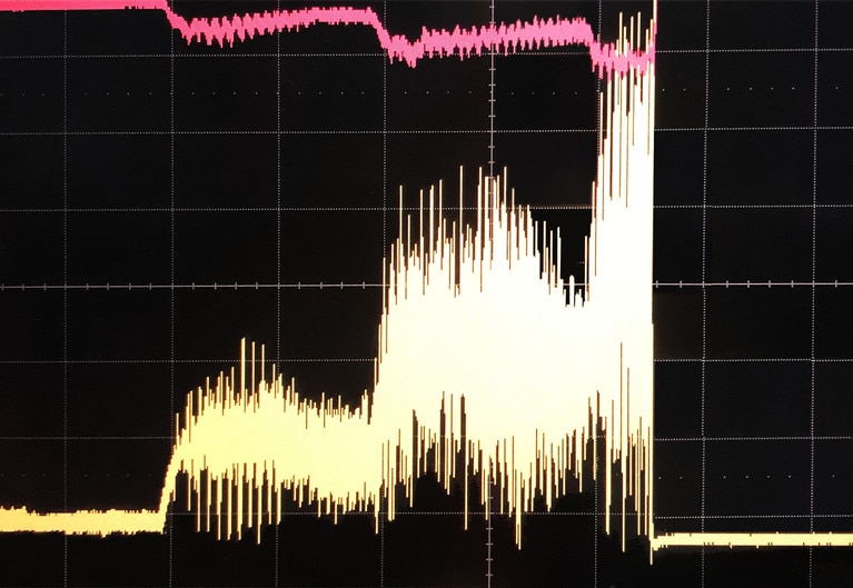
See Figure 8 for example, the 770V input voltage and current supplying four 35A, K = 1/16 fixed-ratio converters (like the ones in Figure 7) are shown. Using Figure 6 as a block diagram, ROUT = 3.5mΩ and ZPDN = 10Ω (including a negligible battery impedance) to power a 48V motor drive.
Placing the converter near the motor-drive makes it see the 10Ω source as only 10/256 = ~40mΩ, for a total 43.5mΩ including ROUT with no 48V cable. The peak current sourced is 14.7A, as the low-impedance converter provides the PWM current peaks in addition to the average current, necessitating it to be specified at the 4 – 5A higher peak-current capability.
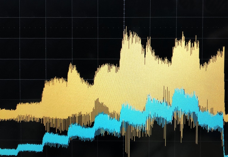
Figure 8: (left) Oscilloscope image at 20ms/div of the 770V input [red] at 100V/div and current [yellow] at 2A/div accelerating a 48V motor through a 6kW [8kW peak] fixed-ratio converter showing acceleration steps and PWM pulses, (right) peak detail at 100µs/div.
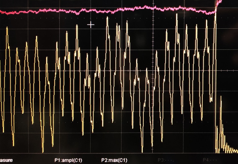
Figure 9 shows impedance reflection in action. A 10µF, 30mΩ RESR input capacitor is used instead of a bulky 10mF, 3mΩ RESR capacitor at the output. This reduced input ripple current on the source cable from 11 to 1AP-P, greatly reducing losses due to the reduction in ac impedance from 10 to ~1Ω. The peak current dropped to 9.75A with a small output LC filter — above the converter’s 8.75A continuous current limit but well within the 14A short term current limit.
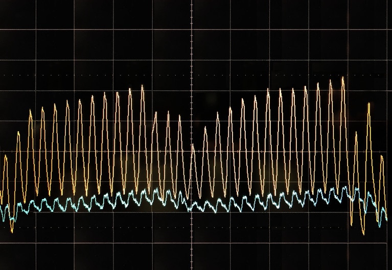
Figure 9: Converter output of 180APK (yellow) at 40A/div, input current (blue) at 2A/div. Ripple is reduced by capacitance placed a the input. (left) 20ms/div (right) 0.1ms/div.
At start up, motor drives and computing boards act as large capacitive loads. Computing cards may have a large array of onboard buck converters, each equipped with bulk input capacitors, and/or additional LC filters. The DC-DC converter powering them needs to have either a generously specified allowable external load capacitance or to be followed by a form of pre-charge circuit to work with large capacitive loads as is often the case powering motor drives with fixed-ratio converters.
This is an often-overlooked item until late in the design. Some regulators, particularly buck-boosts, are also designed for battery charging and allow for a separate current-control loop and/or adjustable soft-start time, allowing for them to be used with massive load capacitances.
During dynamic operation or braking, a motor drive may act as a generator. In our 57V example, the regenerating primary motor drive’s reversing current will charge the battery through the connecting harness, raising its voltage along the path proportionally to the associated impedances, possibly to above 60V. Any DC-DC converter powered by it would then have to be rated not at the commonly available 60V but to a higher voltage.
The schematic in Figure 6 also applies to power distribution networks where a motor drive such is powered by a bidirectional converter, such as our example in Figure 8. Regenerating energy can raise the voltage on both the low voltage and high voltage terminals proportional to ZOUT through the converter. If the converter is unidirectional this regenerative energy is blocked and only the output capacitor COUT is charged. So the regenerative energy and its resulting voltage rises should be limited if possible to stay within the maximum output voltage specification of the converters and COUT, or a brake-circuit can be implemented to absorb the energy.
To optimize performance and increase range, productivity and flexibility, robotic system designers are encouraged to map out the power tree of their application and weigh different types of converter combinations and PDN design strategies. It is advantageous to distribute a higher voltage across a platform and transform it close to point-of-load to the required voltage.
Creative use of Vicor high-density, high-performance fixed-ratio converters modules and buck and/or buck-boost regulator modules likely will achieve optimal performance for each load with efficient and lightweight power delivery. Combining these makes it possible to standardize on highly-efficient, non-isolated end power stages that have a moderately wide input range. These can be connected to higher-voltage battery architectures through fixed-ratio converters deployed with appropriate transfer ratios.
Anna Giasson is an Applications Engineer at Vicor Corp., Andover, MA. She has designed switched-mode AC-DC power supplies with active PFC. She is obtaining her Master's degree in Electrical and Electronics Engineering from Worcester Polytechnic Institute and has a Bachelor's degree in Electrical and Electronics Engineering from Wentworth Institute of Technology in 2015.
Stavros “Steve” Dokopoulos is a field applications engineer at Vicor Corp, Richmond, Virginia. He obtained his Master’s degree in Electrical and Electronics Engineering from Aristotle University of Thessaloniki, Greece, in 1989 and has worked in the power electronics industry since.
Previously published in IEEE Power Electronics, December 2020, as “Rethinking the power delivery networks of mobile robots."
Accelerate your move to a high performance 48V power delivery network
This eBook provides guidance on designing 48V power delivery networks to enhance the performance, efficiency, and reliability of industrial products
Build better UAVs using modular power
Power Delivery Networks (PDN) based on Vicor high performance power modules enable innovative designs for the next generation of UAV development
UAV Market Trends and Power System Seminar 2025 Taipei, Taiwan
Power modules enable top performance and innovation for today’s advanced UAVs
High-efficiency, high-density modules free up space for advanced communications and extend range
High-efficiency class of UAV depend on solar power to meet its long flight time requirements