The future of standardized defense platforms using MOSA, SOSA and VPX open architectures
The future of standardized defense platforms using MOSA, SOSA and VPX open architectures
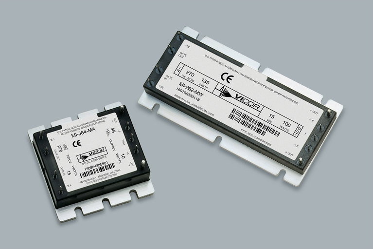
The Maxi, Mini, Micro family of DC-DC converters provides high density, low noise, with advanced power processing. The Maxi, Mini, and Micro converters are compact and efficient, offer wide input ranges, remote sense, enhanced output programmability and low standby dissipation. Low-noise zero-current and zero-voltage switching and advanced power semiconductor packaging provide up to 120W/in3 with low temperature gradients.
Fully encapsulated, Maxi, Mini and Micro series DC-DC converters utilize a proprietary spin-fill process that assures complete, void-free encapsulation making them suitable for the harshest environments. Two grades (H & M), are available with temperatures to –55°C operating and –65°C storage. H & M-Grade modules are qualified to the stringent environmental tests of MIL-STD-810 and MIL-STD-202 and undergo 100% environment stress screening.
Low‑noise zero‑current switching and zero‑voltage switching technology
Output voltage adjusts from 10 to 110%
Input undervoltage lockout
Output overvoltage protection
The future of standardized defense platforms using MOSA, SOSA and VPX open architectures
The future of standardized defense platforms using MOSA, SOSA and VPX open architectures
Delivering higher power density and low noise for New Space applications
Patented power design techniques and architectures needed to deliver optimal power and low noise for space communications applications
Optimizing DC-DC converter stability: AC and transient analysis in simulations of source impedance effects
Learn how to optimize DC-DC converter stability through AC analysis in the frequency-domain and transient analysis in the time-domain
Tech Taipei 2026 High Power Semiconductor Technologies Seminar
Vicor to present high density power conversion accelerating the migration to 48V power delivery networks
Rugged DC-DC converters supporting traditional design
Up to a total of 300W from one, two or three outputs
Rugged input filter module for Maxi, Mini, Micro
MIL output ripple attenuation module
User-defined, modular power solutions for MIL-COTS
A highly flexible system of DC input; power building blocks that can be configured for up to 4 outputs