

Power averaging for counter-UAS systems delivers speed and reliability
Power averaging enables compact, lightweight C-UAS systems by pairing current-limiting DC-DC converters with capacitors to deliver peak pulses reliably


Power averaging uses current-limiting converters and bulk capacitors to reliably deliver peak power pulses to counter-UAS platforms. By sizing systems for average rather than peak demand, it drastically reduces power network size and weight. High-density DC-DC converters make this lightweight, high-performance power delivery possible.
By Dave Berry, Sr. Principal Applications Engineer
Whether detecting or disabling enemy drones or drone swarms, counter-UAS (unmanned aircraft system) platforms rely on power delivery networks (PDNs) that can deliver short, high-power pulses to their load. The challenge, however, is optimizing the source of power to ensure speed and reliability.
In most cases, supporting sustained peak loads requires PDNs with extremely bulky supplies adding size and weight. Unfortunately, Counter-Unmanned Aircraft Systems (C-UAS) are often mobile and battery- or generator-powered, inherently limiting their PDN’s peak power capabilities. While a platform’s pulsed emitter may demand tens of kilowatts for a few hundred microseconds, most C-UAS systems can only provide a small fraction of that.
Power averaging offers an efficient solution. With power averaging, rather than sizing the entire supply for the peak power condition that occurs only for brief periods, a power averaging circuit pairs a current-limiting converter with a bulk capacitor to deliver far more power than the converter alone could supply. With high power density, fast capacitor recharge and safe operation into large bulk capacitance, high-density modular DC-DC converters can make power averaging a reality for C-UAS systems.
One solution for applications where the load is only on for a short duration and is repetitive, is to use a current-limiting converter and a capacitor to supply peak power needs. When configuring such a power system, the designer must take into account the current limit, power limit and stability of the power supply as well as sizing the capacitor properly to keep the voltage drop at the load within its tolerances. Pulsed emitters, radar and LIDAR arrays, and similar pulsed C-UAS loads can take advantage of power averaging to reduce cost, space and weight within the system.
Power averaging configurations are very effective when the load can tolerate a wide input voltage range. This is typically the case where the load is another regulating device — typically a point-of-load converter — or several of these regulating devices.
When the point-of-load (PoL) or load demands power, the capacitor will deliver a greater portion of the load current because the DC converter will go into current limit feeding the capacitor and the load. As the capacitor delivers the PoL or load current, its voltage will begin to fall. The capacitor must be sized so that the voltage across the capacitor stays within the input voltage range of the PoL converter (Equation 1).

Equation 1: C is the hold-up capacitor value, P is the power needed during each pulse. T1 –T2 is the pulse duration. V1 is the starting voltage before the pulse and V2 is the final voltage at the end of the load pulse.
To minimize the capacitance needed the designer can charge the capacitor to the PoL’s maximum input voltage and allow the power draw over the power duration to operate the capacitor down to the PoL’s minimum input voltage.
DC-DC converters are typically designed to regulate voltage up to a maximum power level and therefore have a maximum current and power rating. If the load, such as the radar load in a C-UAS emitter, tries to draw more than the rated current from the supply, the supply typically goes into a current-limiting mode that either folds back the output voltage or shuts down and restarts.
The current limit is typically set just above the maximum rated current so that full power delivery is possible at the voltage set point of the converter. A converter rated for 500W at 48VDC will have a maximum continuous current rating of 500W/48VDC or 10.4A. The current-limiting feature however, may not start until the output current is at 13A.
Current limiting is typically designed for load faults where the converter will see current limit only a few times in its life. If the converter isn’t designed to go into current limit as a normal mode of operation, doing so too frequently can stress components within the converter and shorten the life of the power system.
If the load draws more than the maximum current but below the current limit at the voltage set point, then eventual power system failure can result from chronic overpowering of the supply. Thus, a 500W converter at 48VDC with a current limit set at 13A will be overpowered up to 624W before current limiting starts.
The large bulk capacitance used in power-averaging applications can cause many complications for the DC power system. Upon power-up the larger capacitor, which in many cases can be in the thousands of microfarads, can draw the DC supply into current limit. With the potential problems associated with built-in current limiter, frequently an external current-limiting circuit is required to limit the supply within its maximum current and maximum power ratings.
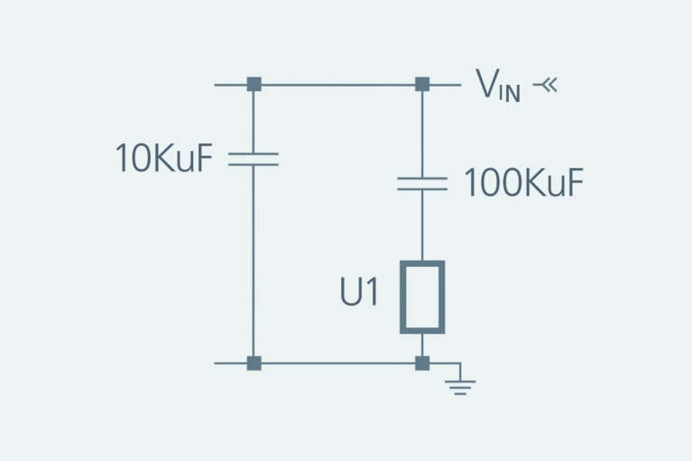
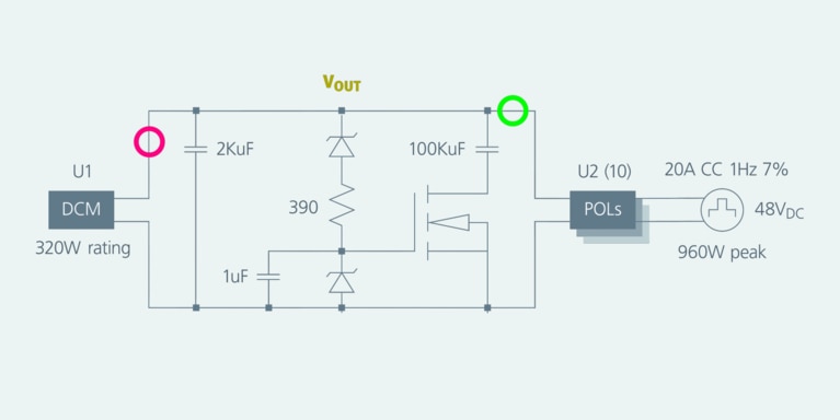
Counter-UAS power designers can pre-charge the capacitor or add series resistance that limits the current at start up, which can be shorted out once the external current limiting circuit is active (Figure 1). Pre-charging and current-limiting circuits can be complex and they take up valuable board real estate. The external current-limiting circuits must also be fast enough to catch an overcurrent event.
Figure 1: 10mF cap is the capacitor needed for DCM operation. The 100mF capacitor is the pulse hold-up capacitor. U1 is the capacitor introduction circuit.
This can be challenging because even a few switching cycles can cause an overcurrent event. Once the DC supply successfully powers up, the power system must be stable. With some DC-DC converters, the large capacitor can destabilize the voltage control loop, which can cause supply or system failure. This potential stability issue can be overcome with access to the control loop of the power system, but this requires complex and time-consuming engineering work.
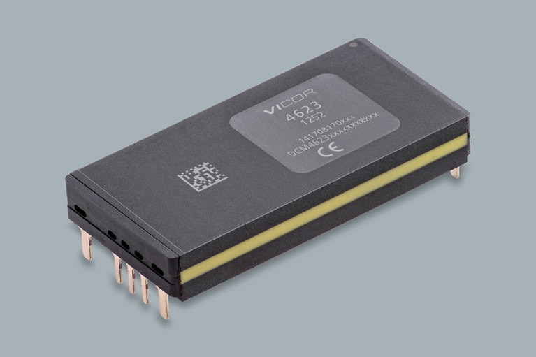
The peripheral circuitry can become very complex if the power converter isn’t designed to handle a large capacitor at its output. Vicor DCM™ DC-DC converters, however, are designed to handle large amounts of capacitance at their outputs and can operate within their maximum current rating and power rating even when driving capacitance values as large as 10 millifarads. Even larger capacitance can be handled if it is switched in during start up. The DCM has a safe current-limiting feature which means it can safely operate at the voltage set point of the module because the DCM can deliver more than its rated power for short durations (Figure 2).
Figure 2: Vicor DCM4623 is power dense and has a safe current-limiting feature for counter-UAS platforms. Vicor DCM DC-DC converters are designed to handle large amounts of capacitance at their outputs and can operate within their maximum current rating and power rating even when driving capacitance values as large as 10 millifarads.
At start up, the DCM will drive the capacitor up to voltage while staying within its specified operating area. Once the capacitor is charged, the control loop of the converter is designed to be stable during normal operation.
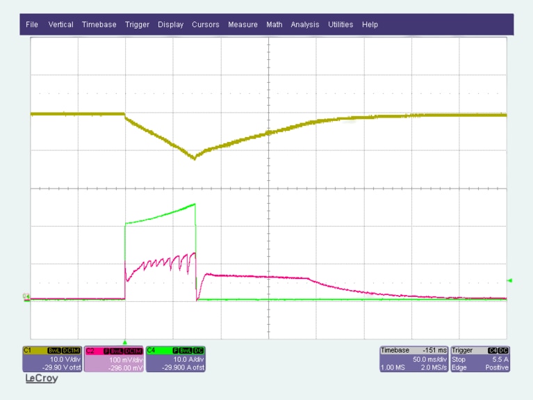
If the application is designed for power averaging, the initial power burst into the downstream PoLs will be greater than the converter’s capability. The PoL input current will be delivered from the voltage source that has the largest potential. Due to the ESR of the capacitor, the converter’s output can have the larger potential and will deliver the initial surge of current until its output drops because of current limit. DCMs are designed to handle this surge current until its internal current limit takes over. Once the DCM’s voltage drops, the current demand will then be satisfied by the capacitor. The capacitor can be sized to deliver much more current than the DC converter module. Once the PoL or load current demand is over, the DC converter has to recharge the capacitor to its initial voltage so it can be ready for the next current demand (Figure 3).
Figure 3a (top): The yellow trace (C1) shows the VOUT voltage of the DCM that feeds the downstream U2 loads. The red trace (C2) shows the averaged output current of the DCM. The scale of the red trace is 10mV/A. The green trace (C4) shows the pulsed load current.
Figure 3b (bottom): The scope plot and block diagram of a power system designed for power averaging explains how the systems operates. In this example, the DC converter module has its output set to 50VDC and the converter module is rated for 320W of continuous power. The downstream PoL converters are supplying a total 20A at 48VDC or 960W of load power. The load frequency is 1Hz and the duty cycle is 7 per cent so the load is on for 70ms. When the PoLs begin to deliver power to the load, they draw energy from the 100 millifarads capacitor and the DCM. The DCM will go into protective current limit and the capacitor will supply the bulk of the power with the DCM in current limit. After the load demand is complete, the DCM will recharge the capacitor to its initial voltage.
The challenges of protecting borders from threats are perpetually evolving. However, the importance of speed and reliability in responding to threats will never change. Configuring a power delivery network that can respond under the most daunting conditions is essential and saves lives.
Power supplies configured for power averaging enable fast response and reduce the size, weight and the cost of power systems. Reduced size and weight, of course, increase mobility and flexibility in the field which is always an added benefit. Deploying a power averaging approach, where the load is on for a short, periodic duration, is the optimal profile of reliable counter-UAS detection and response system.
The support circuitry can be minimized if the DC converter module is designed to operate safely within its current-limit and power limit maximums. Sizing the power system for the average power also helps eliminate the support circuitry and hardware needed for power systems sized for continuous peak-power delivery. This also helps the designer maintain the system space and weight constraints.
In the field, every detail matters – speed, agility, reliability, size and weight. When designing C-UAS platform, fighting for every kilogram and watt is the difference between a power system that fits within the application and one that does not.
This article was originally published by Components in Electronics.
David Berry has a Bachelor of Science in Electrical Engineering from Union College in Schenectady, NY. He was a former magnetics designer specializing in impedance matching transformers, and now works for Vicor Corporation as a Sr. Principal Applications Engineer. He has been working in component power design for the Aerospace and Defense market for over 29 years.
Dave Berry, Sr. Principal Applications Engineer
Power averaging for counter-UAS systems delivers speed and reliability
Power averaging enables compact, lightweight C-UAS systems by pairing current-limiting DC-DC converters with capacitors to deliver peak pulses reliably
开放标准 VPX 正在美国、欧洲及全球各地迅速普及
自 2010 年以来,传感器开放系统架构(SOSA)标准帮助美国军方蓬勃发展。了解 Vicor 如何在这个新领域提供更多服务
實現無縫互操作性和長期可升級性
瞭解所需要的規格,以及可以接受哪些權衡,選擇最符合您設計要求的產品
快速修改標準 SOSA 電源,滿足應用掉電保持(hold-up)要求
瞭解 Vicor 如何通過配寘後的標準 SOSA 電源為車輛防護與對抗系統供電