


Optimizing DC-DC converter stability: AC and transient analysis in simulations of source impedance effects
Learn how to optimize DC-DC converter stability through AC analysis in the frequency-domain and transient analysis in the time-domain
Tutorial by Jonathan Siegers, Principal Applications Engineer and Vamshi Domudala, Application Engineer
The previous tutorials in this series showed first how a modular design strategy makes building reliable, adaptable, and high-performing power delivery networks (PDNs) possible when speed is a priority, and second how to design appropriate filtering to meet the needs of DC-DC systems based on switching power modules. This third tutorial will address stability issues that originate from the interconnection between the power source and power module through the filtering components and distribution line impedances.
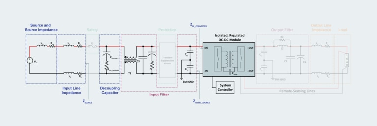
Complete system design based around a modular DC-DC converter requires filtering; filtering impacts some stability concerns that must be addressed by decoupling the source and the converter (blue elements of the system diagram).
Complete system design based around a modular DC-DC converter requires filtering; filtering impacts some stability concerns that must be addressed by decoupling the source and the converter (blue elements of the system diagram).
To analyze overall stability of a DC-DC converter system, first break it down into two subsystems of source and load. In this representation, the “load” subsystem is the DC-DC converter itself. Source impedance, input line impedance and the input filter are part of the source subsystem.
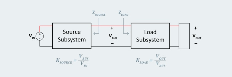
To analyze stability, idealize the system as a block diagram representation of interacting source and load subsystems.
To analyze stability, idealize the system as a block diagram representation of interacting source and load subsystems.
The source and load subsystems can be considered inherently stable on their own. But when the two are interconnected (at VBUS), they can interact in ways that produce oscillations, leading to unstable operation of the system.
To analyze this type of system for stability, consider the frequency-dependent finite source impedance that the input filter and other upstream components presents to the DC-DC converter. The source subsystem, having a finite output impedance, supplies power to the load subsystem that has its own finite input impedance. The ratio of these impedances is the key to analyzing system stability as characterized by the Middlebrook stability criterion, which states that a system is stable if the magnitude of the load subsystem’s input impedance is larger than the magnitude of the source subsystem’s output impedance.
The ratio is defined here as the minor loop gain of the system: the source impedance, which is looking back into the source subsystem — including the input filter, any interconnect impedance, as well as the power source output impedance itself — to the load input impedance looking into the DC-DC converter.

Based on this relationship, what we define is a ratio (TMLG) wherein the source impedance must be less than the load impedance for the system to be stable.

If this ratio is not maintained, the result will be an improperly damped system that will exhibit erratic operation and possibly serious instability. Effectively, the system can form a negative-resistance oscillator between the source and the DC-DC converter. This can allow some system dynamics to cause an oscillation. Clearly, this is not what a well-designed system should do.
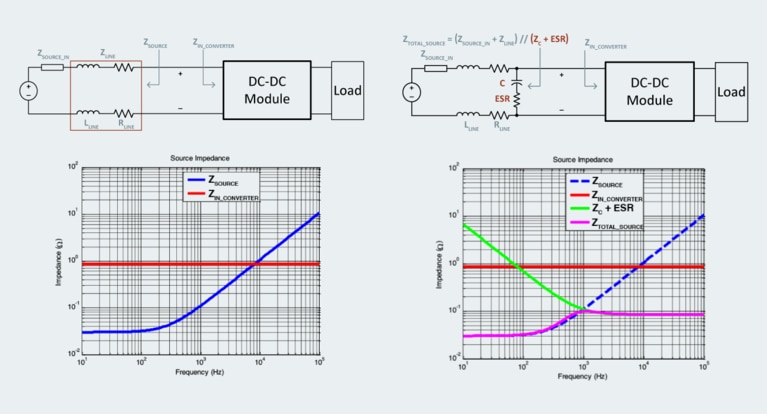
Decoupling the source impedance from the load impedance is required to ensure oscillations do not destabilize the system. A decoupling capacitor placed at th input side of the DC-DC module is an effective way to accomplish this. To see it clearly, consider the example of a power source simplified into its Thévenin equivalent circuit, an ideal voltage source, and its impedance shown as a discrete impedance block, as in the complete system design figure above. Additionally, the distribution line impedance, which includes the inductance and resistance of the cabling to the DC-DC converter, also forms part of the source subsystem.
Partition the system at the bus between the DC-DC converter and the system’s source to clearly differentiate the two impedances: the output impedance looking back into the source and the input impedance going in to the DC-DC converter. Assume for simplicity that the DC-DC converter’s input impedance is resistive only and therefore fixed for all frequencies, while the source impedance has a characteristic of resistance at low frequency and inductance at high frequency. It is at the point of transition into high-frequency operation that this stability analysis is most critical due to the increasing output impedance of the inductive source subsystem.
Insertion of capacitance with ESR to keep input impedance to the DC-DC converter above the source impedance at high frequency, ensuring overall system stability.
Insertion of capacitance with ESR to keep input impedance to the DC-DC converter above the source impedance at high frequency, ensuring overall system stability.
To maintain stability at high frequency, the system must provide an additional impedance element to modify the source impedance that the DC-DC converter encounters to prevent instability. This is fairly simple to accomplish with the addition of a capacitance and its equivalent series resistance (ESR), which forms part of a damping network.
The capacitive impedance (green trace) placed as a shunt between the source output impedance and the input impedance of the DC-DC converter decreases as frequency increases, bypassing the inductance of the source and creating an overall low equivalent output impedance from low frequency up to high frequency for the DC-DC converter to operate from.
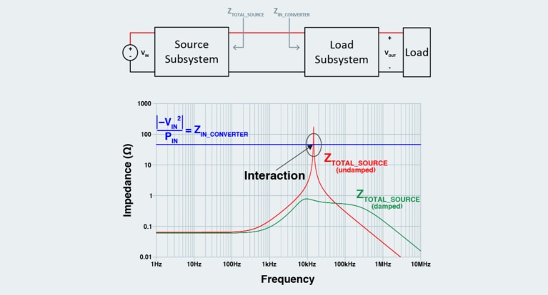
The addition of an input filter to a regulated DC-DC system can modify the apparent source output impedance in such a way as to create an unstable system. The filter components can produce interactions that violate the Middlebook stability criterion and lead to unstable system operation and oscillations. In an unstable system, load steps also cause perturbation, resulting in undesirable transients on the input voltage bus.
Define the input impedance of the regulated DC-DC converter at the minimum input voltage and maximum input power for which the system will operate. This yields a resistive approximation of the input impedance to the DC-DC converter, just as in the previous example. The system stability can now be evaluated by comparing the resistive approximation of the regulated DC-DC converter input impedance with the source’s output impedance (which includes additional filtering components).
In the example analysis in the following figure, the initial design of the input filter indicates that some interaction of the source and load impedances occurs due to a resonant peak in the total source impedance between 10kHz and 11kHz; this is caused by lack of damping in the composite source and input filter frequency response. In this frequency range, the ratio of source impedance and load impedance is greater than unity; this system’s instability can be expected.
With proper damping, however, the resonant peak magnitude can be reduced to ensure that the input impedance of the DC-DC converter and the source’s output impedance are properly decoupled, satisfying the Middlebrook stability criterion. With the filter appropriately damped, this system achieves good overall performance and avoids undesirable oscillations and instability.
The addition of an input filter to the system requires additional impedance analysis and adjustment to the damping network to ensure stability with worst-case input impedance to the DC-DC converter.
The addition of an input filter to the system requires additional impedance analysis and adjustment to the damping network to ensure stability with worst-case input impedance to the DC-DC converter.
At this point, the DC-DC system’s design meets the application’s needs: the architecture and DC-DC module(s) have been chosen, appropriate filtering to mitigate module noise effects has been added, and now overall system stability at high frequency and worst-case conditions has been addressed. With a stable and effective system in place, protecting the system from destructive transient events and protecting neighboring systems from the effects of catastrophic failure are the next area of system design. We will consider those factors in the next tutorial.
Also in this series:
How to design modular DC‑DC systems, part 1: four stages of design
How to design modular DC‑DC systems, part 2: filter design
How to design modular DC‑DC systems, part 4: safety protection systems
How to design modular DC‑DC systems, part 5: load considerations
Industries: Industrial applications
Article: Power delivery networks at a crossroads
White paper: Attributes of high‑performance power module packaging
Optimizing DC-DC converter stability: AC and transient analysis in simulations of source impedance effects
Learn how to optimize DC-DC converter stability through AC analysis in the frequency-domain and transient analysis in the time-domain
Power modules simplify creepage and clearance design solutions for electric vehicles
Overmolding is the key to solving arcing issues in 48V automotive power systems
Current multipliers: The obvious choice for powering AI processors and other demanding applications
AI processors need to handle low-voltage, high-current demand, which can cause power system bottlenecks. Learn how current multiplication can change that.
High-performance ZVS buck regulator removes barriers to increased power throughput in wide‑input-range point-of-load applications
Today's higher performance applications require more than what conventional regulators can offer. Learn how ZVS topology can boost your performance.

